background image

Hearthstone Quality Home Heating Products, Inc.                                                   

                       WAITSFIELD Model 8770  

38 


Any  safety  screen  or  guard  removed  for 
servicing an appliance must be replaced prior to 
operating  the  appliance.   

Tout  écran  ou 

protecteur  retiré  pour  permettre  l’entretien  de 
l’appareil  doit  être  remis  en  place  avant  de 
mettre l’appareil en marche. 


Cleaning 


WARNING: DO NOT CLEAN THE UNIT WHEN HOT.  


The unit should receive regular cleaning  on, under, 

and around the stove to prevent the buildup of dust 

and  lint.  The  exterior  surfaces  of  the  unit  can  be 

cleaned using soap, water, and a soft cloth. Do not 

use abrasive or chemical cleaners and take care not 

to scratch the glass or enamel finish (if so equipped) 

when  cleaning  the  unit.  The  use  of  chemical  wax 

based  cleaners  or  polishes  are  not  recommended 

due to the potential for discoloration of the castings, 

or  enamel  when  the  residue  of  the  cleaners  or 

polishes  is  exposed  to  heat.  Excessive  buildup  of 

dust,  spider  webs,  or  room  air  contamination  may 

cause odors when the stove is hot.  

 
Monthly (or as needed):


Glass Cleaning 

As  fuel  gas  may  contain  some  impurities;  it  will  be 

necessary  to  clean  the  inside  of  the  glass 

occasionally.  Do  not  use  abrasive  cleaners. 

Scratching the glass will weaken the integrity of the 

glass. 

Do not clean the glass when hot!

 Allow the 

glass to cool and apply a mild window cleaning fluid. 

Special  gas  appliance  window  cleaner  is  available 

from your local Hearthstone dealer. 


WARNING:  DO  NOT  OPERATE  THIS  APPLIANCE 
WITH  THE  GLASS  PANEL  REMOVED,  CRACKED, 
OR  BROKEN.  DO  NOT  SUBJECT  THE  GLASS  OR 
ITS  FRAME  TO  ABUSE,  SUCH  AS  STRIKING  OR 
BENDING.  REPLACEMENT  OF  THE  GLASS 
PANEL  SHOULD  BE  DONE  BY  A  LICENSED  OR 
QUALIFIED  SERVICE  PERSON.    REPLACE  WITH 
MANUFACTURER-APPROVED 

FRONT 

GLASS 

ONLY. 

NE  PAS  UTILISER  L’APPAREIL  SI  LE 

PANNEAU  FRONTAL  EN  V

ERRE  N’EST  PAS  EN 

PLACE,  EST  CRAQUÉ  OU  BRISÉ.  CONFIEZ  LE 
REMPLACEMENT 

DU 

PANNEAU 

À 

UN 

TECHNICIEN AGRÉÉ. 


NOTE: 

If the venting system is disassembled for any 

reason, re-install per the instructions provided in the 

venting section of this manual. 


Annually:


Clean Firebox, Pilot, & Burner Assembly 

The firebox requires periodic cleaning to prevent the 

accumulation of dust, lint, and other debris. To clean 

the firebox, set the switch to the “OFF” position, and 

turn off the gas supply to the valve. When the unit is 

cool, remove the front panel and glass (see page 9 

for  Firebox  Access  instructions)  and  carefully 

remove  the  decorative  ceramic  log  set,  taking  care 

not to damage the logs or chip the enamel cast iron. 

Remove all ember material. Clean the firebox baffle, 

burner,  and  carefully  vacuum  the  entire  surface  of 

the log set with a soft brush attachment. Thoroughly 

vacuum the ports (holes) along the top of the burner, 

and the pilot assembly. 
With the decorative ceramic logs out of the firebox, 

reseal the firebox and briefly light the unit according 

to  the  lighting  instructions  described  on  page  20. 

Check to ensure a proper flame is burning from each 

burner  port.  The  pilot  flame  should  be  burning 

properly as shown in 

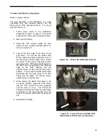
Figure 17.


NOTE: Do not operate the unit for more than 
1-2  minutes  without  the  log  set  in  place.  
Turn  the  unit  off  by  setting  the  switch  to 
“OFF”, and turning off the gas supply to the 
valve. Allow the unit to cool. 

Check  and  clean  any  burner  ports  that  are  not 

burning, or not burning properly. Clean burner ports 

using  a  soft  brush  or  vacuum  cleaner.  If  the  pilot 

flame height needs adjustment, it should be adjusted 

by qualified service personnel as described on page 

21. 
Complete  the  cleaning  procedure  by  carefully 

placing the log set within the firebox as described on 

pages 25-27. Reattach the glass to seal the firebox 

and  install front/top castings. Turn on the gas,  light 

the  unit  and  check  for  proper  operation.  Flame 

patterns should look similar to the flames in 

Photo 1, 

page 29. 

 Regularly check to ensure the area around 

the  Waitsfield  is  kept  free  from  combustible 

materials, gasoline, and other flammable vapors and 

liquids.  Check  that  the  flow  of  combustion  and 

ventilation air is not obstructed.  

 
Battery Replacement 


WARNING: DISCONNECT POWER TO THE UNIT 
AND SHUT OFF THE GAS SUPPLY TO THE 
VALVE BEFORE REPLACING ANY BATTERIES.  


Hearthstone  recommends  replacing  all  batteries  at 

least  every  season.  Keep  a  supply  of  good  quality 

Summary of Contents for Waitsfield DX 8770

Page 1: ...r 911 A qualified installer service agency or gas supplier must perform installation and service of this appliance In the Commonwealth of Massachusetts all installation of gas lines and gas fittings must be performed by a licensed gas fitter or licensed plumber AVERTISSEMENT ASSUREZ VOUS DE BIEN SUIVRE LES INSTRUCTIONS DONNÉ DANS CETTE NOTICE POUR RÉDUIRE AU MINIMUM LE RISQUE D INCENDIE OU POUR ÉV...

Page 2: ...Intentionally Blank ...

Page 3: ...ormation 16 Gas Supply Connections 17 Gas Connections 18 Initial Leak Check 18 Pre Ignition Checks 18 Initial Lighting Instructions 20 Ignition Instructions 20 Pilot Adjustment 21 Outlet Pressure Adjustment 21 Minimum Flow Adjustment 21 LP Conversion 22 Firebox Log Set Placement 25 Installation 25 Removal 27 Air Shutter 28 Restrictor 28 Maxitrol GV60 Control System Features 29 Sync Receiver to Rem...

Page 4: ... lifting slightly and pulling forward free of the stove Set panel aside on a soft surface Locate and grasp receiver body Pull receiver straight forward from the mounting bracket firmly but slowly As soon as the receiver can be rotated free of the mounting clip turn over counter clockwise until battery cover can be accessed Remove battery access cover lay red ribbon across the battery tray and inst...

Page 5: ...a safe place as proof of purchase Serial Number Fuel type Natural Gas Liquid Propane Sold by Date of Purchase Address Phone E mail Website Installed by Date of Installation Address Phone E mail Website Gas Supplier Address Phone E mail Website Read this Owner s Manual before installing or operating your Waitsfield Retain this manual for future reference SERVICE RECORD Date Who Performed Work Work ...

Page 6: ...ating Products Inc 317 Stafford Ave Morrisville VT 05661 8695 USA www hearthstonestoves com Waitsfield DX Dimensions Specification NG LP Input rating Btu hr 0 2000 ft 37 000 37 000 Input rating Btu hr 2000 4500 ft 37 000 37 000 Orifice size DMS 0 2000 ft 45 45 53 f 57 r Orifice size DMS 2000 4500 ft 45 45 53 f 57 r Man press LO setting in w c kPa 2 7 0 67 10 7 2 67 Man press HI setting in w c kPa ...

Page 7: ... on remote control Part Description 8762 0010 Matte Black 8762 0020 Brown Enamel 8762 0030 Basil Enamel Read this Owner s Manual Operate and maintain this gas heater according to the instructions in this manual For your safety and years of trouble free operation read this manual in its entirety Heater Must Be Installed and Maintained By Qualified Service Personnel Verify the gas connections and ve...

Page 8: ...he rating plate This appliance is not convertible for use with other gases unless a certified kit is used Cet appareil doit être atilisé uniquement avec les types de gas indiqués sur la plaque signalétique Ne pas l utiliser avec d autres gas sauf si un kited conversion certifié est installé WARNING THIS GAS APPLIANCE MUST NOT BE CONNECTED TO A CHIMNEY FLUE SERVING A SEPARATE GAS OR SOLID FUEL BURN...

Page 9: ... log or burner material supplied with the Waitsfield is damaged or parts are missing they must be replaced with the same or approved Hearthstone replacement parts These components affect the combustion quality and safety of the heater Do not replace ceramic logs the burner or baffle with unapproved ceramic components or any other material We recommend you always wear gloves and safety goggles whil...

Page 10: ...pieds 0 610 m seulement Items Required for Installation External regulator for propane LP only LP conversion kit for propane only Piping which complies with local codes Pipe sealant approved for use with propane LP resistant to sulfur compounds Manual shutoff valve Sediment trap see page 20 Pipe wrench Phillips head screwdriver 7 16 inch wrench 5 23 4mm allen wrench Other parts as required by loca...

Page 11: ...nd off of the stove body and set aside Figure 2 3 Remove glass and frame by holding to the stove with one hand while pulling glass retention spring clips forward and lifting slightly clear of the stove glass frame one at a time Figure 3 4 Gently release pressure on the glass frame and allow to tilt outward Gently grasp and lift up and off of the stove Figure 4 While glass and retention frame are r...

Page 12: ...STIBLE MATERIALS EXPOSED TO HEAT BY THIS PRODUCT THEREFORE AN ASSESSMENT MUST BE MADE BY THE INSTALLER TO PREVENT CONSEQUENTIAL DAMAGE OF WALLS AND FLOORING Hearth Requirement Floor Protection You can place the Waitsfield directly on any non combustible surface or on a wood floor When placing the Waitsfield on any other type of combustible surface you must install a panel made of metal wood stone ...

Page 13: ...E BURNER There are two types of venting configurations approved for use with this appliance Vertical Venting Vertical Termination Vertical Venting Horizontal Termination Pipe Clearances to combustibles 1 to vertical runs 1 below and to the side of horizontal runs 2 from the top of horizontal runs Vertical Venting and Termination The Waitsfield 8770 is approved for venting vertically through a roof...

Page 14: ...stallation has been tested and approved by Intertek Testing Services with an appropriate test The code authority having jurisdiction must be consulted prior to proceeding with this installation method See examples below Figure 9 Existing Chimney Venting Options Horizontal Termination The termination must fall within the area shown in Figures 11 12 A minimum of 36 rise is required directly off the ...

Page 15: ...BETWEEN THE VENT CAP AND THE EXTERIOR WALL 4 Install the horizontal vent termination on the outside of the wall Ensure both of the retaining straps extend through interior wall thimble Before attaching the vent termination to the outside of the house run a bead of non hardening mastic around its outside edges so as to make a seal between it and the wall The arrow on the end cap should point up Sec...

Page 16: ...cm CAN We strongly recommend 12 inches particularly where strong winds prevail H Not to be installed within 15 feet 4 5m above a meter regulator assembly within 3 feet 91cm horizontally from the center line of the regulator I Clearance to service regulator vent 3 feet 91cm J Clearance to non mechanical air supply inlet to building or the combustion air inlet to any other appliance 12inches 30cm mi...

Page 17: ...Hearthstone Quality Home Heating Products Inc WAITSFIELD Model 8770 16 Figure 12 Venting Termination ...

Page 18: ... ERRORS CAN CAUSE IMPROPER AND DANGEROUS OPERATION VERIFY PROPER OPERATION AFTER SERVICING ATTENTION AU MOMENT DE L ENTRETIEN DES COMMANDES ÉTIQUETEZ TOUS LES FILS AVANT LE DÉBRANCHEMENT DES ERREURS DE CÂBLAGE PEUVENT ENTRAÎUN FONCTIONNEMENT INADEQUATE ET DANGEREUX The proper location of wire connections is shown in the following figure Figure 13 Waitsfield 8770 Wiring Diagram ...

Page 19: ...S CODES D INSTALLATION CAN CGA B149 NFPA Code and Hearthstone require the use of a dedicated sediment trap just upstream of the unit Damage to the valve or other components due to the lack of a sediment trap are not covered by warranty see figure 14 High Altitude Installations For high altitude installations consult the local gas distributer or the authority having jurisdiction for proper rating m...

Page 20: ...eak detection method around the diaphragm flanges pipe connections seal cap and all other joints Bubbles indicate a leak 2 If no leakage is detected proceed with the instructions listed on page 20 to light the main burner and perform a secondary leak check of the appliance gas supply system 5 If a leak is detected tighten pipe connections including adapters according to GAS CONNECTIONS page 18 WAR...

Page 21: ... is placed in the appliance the surrounding metal can reduce reception considerably The position of the antenna on the receiver also influences reception NOTICE The antenna must not cross or come into contact with the ignition wire This will render the receiver inoperable WARNING ELECTRIC SHOCK HAZARD Read these instructions carefully Failure to follow them could result in property damage personal...

Page 22: ...ve and set on a non marring surface 4 Locate and turn the MANUAL Knob on the valve clockwise to the MAN position see Figure 16 5 Turn the Main Valve knob to OFF 6 Using a pen or other device that will reach through the MANUAL Knob cut out gently press the pilot button and hold it in the down position 7 After a ten second wait push the piezo igniter button on the valve every three seconds until you...

Page 23: ...sed by turning clockwise pressure regulator models or decreased by turning counter clockwise 4 After adjustment replace the plug 5 If no other adjustments are required close pressure tap s by turning the screw s fully clockwise until snug Check all connections pressure tap s for leaks 6 If the desired outlet pressure or flow cannot be achieved by adjusting the gas valve check the gas valve inlet p...

Page 24: ...riving and seat it fully in the valve Figure 18 GV60 Valve Top 6 Loosen the valve mounting bracket front two screws and swing the front of the valve assembly down 7 Using a 4mm 5 32 allen wrench loosen and remove the existing low pressure NG screw by turning counter clockwise until it spins freely It may be necessary to grasp the screw head with your fingernails or gently pry it free of the valve ...

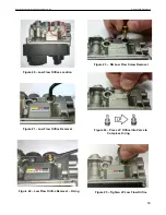
Page 25: ... Model 8770 24 Figure 20 Low Flow Orifice Location Figure 21 Low Flow Orifice Removal Figure 22 Low Flow Orifice Removal O ring Figure 23 NG Low Flow Screw Removal Figure 24 Press LP Orifice into Valve to Compress O ring Figure 25 Tighten LP Low Flow Orifice ...

Page 26: ...d the front of the pilot tower and the letters NAT should be visible on the upper horizontal surface see Figure 26 Slide the gate backward in the Pilot Tower by pushing on the upturned edge by the NAT lettering until the upturned edge is flush with the Pilot Tower surface You will see the NG LP Pilot Gate protruding from the back edge of the Pilot Tower and the letters LP will be visible separated...

Page 27: ...e off position Manual Mode 1 Remove valve access panel 2 Turn the Main Valve Knob clockwise to OFF 3 Turn the ON OFF switch on the valve to OFF 4 Replace valve access panel 5 Turn the gas supply valve to the off position FINAL CHECK Observe several complete cycles to ensure proper operation During these cycles the electronics will determine the optimum ignition sequence timing Log Set Placement Pl...

Page 28: ... 3 Place Log 2 into the channel in the burner with the narrow end resting on log 1as shown Figure 32 Log 2 in Position 4 Place log 3 as shown Figure 33 Log 3 in Position 5 Place log 4 on top of log 1 as shown Figure 34 Log 4 in Position 6 Gently place Log 5 in the indentation on the burner and rest it on log 4 as shown Figure 35 Log 5 in Position 1 1 2 2 1 3 1 2 1 4 3 5 4 1 1 1 3 1 2 1 ...

Page 29: ...ion then the air shutters may need adjusting To determine if an air shutter needs adjustment it is necessary to view the flame pattern with the burner output set at its highest setting Allow the unit to operate for at least 10 minutes to allow the entire unit to reach temperature and for the flame pattern to stabilize Generally the more air open shutter in the mixture the bluer the flame Less air ...

Page 30: ...t unless technically qualified to do so Restrictor Plate The restrictor plate is used to control excess draft if necessary Controlling the draft also changes the aesthetics of the flame The restrictor plate has an unlimited range of settings see Figures 40 41 The adjustment point is on the top center of the firebox accessible with the top casting removed Restrictor Plate Position The restrictor pl...

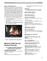
Page 31: ...ion control according to CSA approval see label for certification FUELS CSA Suitable for natural manufactured mixed gases liquefied petroleum gases and LP gas air mixtures APPROVALS CSA ANSI Z21 78 CSA 6 20 for U S Canada ANSI Z21 20 CSA 6 20 for U S Canada PRESSURE DROP CAPACITY CSA 1 W C at 65 000 BTU hr RANGE OF REGULATION CSA 10 000 to 85 000 BTU hr REGULATOR ADJUSTMENT CSA 3 W C to 5 W C 7 5 ...

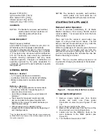
Page 32: ...power outage Without using a mains adapter battery replacement is recommended at the beginning of each heating season Only the Mertik Maxitrol AC Mains Adapter or one preapproved by Mertik Maxitrol can be used Use of other adaptors can render the system inoperable NOTICE The handsets receivers wall switches switch panels and touch pads are not interchangeable with previous electronics STARTING THE...

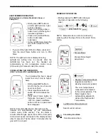
Page 33: ... wait three 3 minutes and repeat step 8 If the main burner does not ignite after a repeat attempt STOP ALL ATTEMPTS TO LIGHT THE MAIN BURNER TURN THE MANUAL KNOB TO ON SHOT OFF THE GAS SUPPLY VALVE AND CALL AN AUTHORIZED SERVICE TECHNICIAN 11 Once the main burner is ignited replace the access panel Further adjustments to the flame height are controlled by turning the Main Valve knob clockwise for ...

Page 34: ...es to high fire HI will be displayed TURNING FRONT BURNER ON OFF ONLY on Bristol 8763 and Waitsfield 8770 NOTE The latching solenoid valve cannot operate manually If the battery runs down it will remain in the last operating position During normal operation the solenoid valve will be reset to the ON position when the GV60 is switched OFF remotely WARNING If the appliance will not operate follow th...

Page 35: ...croll to the fan icon Fan and Level icons flash Press large flame button to switch ON and increase fan speed Press small flame button to Decrease fan speed To turn OFF fan press small flame button until all 4 speed level bars disappear NOTE 8 seconds after the fan has been set the handset will automatically go into temperature control mode CSA version The fan starts 4 minutes after the gas opens f...

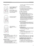
Page 36: ...F 12 HOUR CLOCK Press OFF and small flame button until display changes from Fahrenheit 12 hour clock to Celsius 24 hour clock and vice versa SETTING THE TIME The Time display will flash after either a Installing the battery or b Simultaneously pressing the large flame and small flame buttons Press large flame button to set the hour Press small flame button to set the minute Press OFF or simply wai...

Page 37: ... increase Nighttime Setback Temperature Press small flame button to decrease Nighttime Setback Temperature Press OFF or simply wait to complete programming SETTING PROGRAM TIMERS Default Settings Select Timer Mode by briefly pressing the Set button until P1 and the crescent moon appear Setting P1 ON Time Hold the SET button until P1 and the sun icon displayed and the time flashes Set the hour by p...

Page 38: ...no Motor Movement Manual Model Temperature Timer Mode The valve will turn to pilot flame if there is no change in flame height for a 6 hour period In Temperature Timer Mode if the ambient room temperature changes the flame height will adjust automatically to maintain set temperature and the fire will continue to function normally The valve will turn to pilot flame if the set temperature and the am...

Page 39: ... this manual Annually Clean Firebox Pilot Burner Assembly The firebox requires periodic cleaning to prevent the accumulation of dust lint and other debris To clean the firebox set the switch to the OFF position and turn off the gas supply to the valve When the unit is cool remove the front panel and glass see page 9 for Firebox Access instructions and carefully remove the decorative ceramic log se...

Page 40: ...rtante de poussière Il est essentiel que les compartiments abritant les commandes les brûleurs et les conduits de circulation d air de l appareil soient tenus propres As Needed Glass and Gasket Replacement In the event that you need to repair or replace a cracked or broken glass order kit 97 58621 complete side glass assembly with frame or 97 58620 complete side glass assembly with frame and use t...

Page 41: ...cting paper away from one end Starting at the middle of the bottom edge of the glass apply the gasket centered on the edge of the glass Continue to wrap the gasket loosely around the edge until you meet at the starting point Adjust the gasket so the ends do not overlap If the gasket length is too long trim the excess Do not leave ends with ragged edges 4 Firmly and evenly fold the gasket around th...

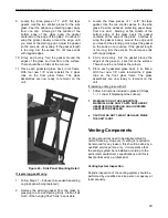
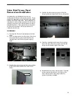
Page 42: ...enience Installation 1 Remove the front valve access panel and set aside 2 From a prone position to either side of the stove look under the stove and up behind the side casting bottom skirt for two square hanging holes 3 Position the privacy panel so the bump out tabs is facing the valve toward the center of the stove 4 Position the side privacy panel such that the hanging tabs are aligned with th...

Page 43: ...6 Gas Manifold 3160 200 Exhaust Manifold Gasket 3160 228 Flue Exhaust Gasket 3160 152 Pilot Gasket Kits 3160 150 Heat Exchanger Gasket 97 67500 Log Set 3160 108 Delayed Ignition Relief Gasket Top 97 58621 Side Glass Assembly 3160 105 Delayed Ignition Relief Gasket Rear 97 58620 Front Glass Assembly 3160 081 x 1 8 Gasket Tape 97 56701 LP Conversion Kit 3170 150 Platinum Bright Embers 97 56700 NG Co...

Page 44: ...t after carefully following lighting instructions A Low or too high gas pressure B Faulty connections C Pilot dirty or plugged D Thermocouple damaged E Thermocouple Interrupter circuit damaged A Check for proper inlet pressure for the fuel gas in use B Check connections on the valve C Clean or replace the pilot assembly D Check for appropriate MV at thermocouple interrupter E Check thermocouple in...

Page 45: ...tem may be too restrictive or blocked the rate at which the exhaust leaves draft determines the rate at which the combustion air is delivered Poor draft results in insufficient air delivery or a restricted exhaust Correct air intake exhaust flow system B1 Clear ports B2 Clear obstructions B3 Clear obstructions C If gas pressures are correct and the flames stay the same adjust the air shutter for a...

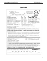
Page 46: ...Hearthstone Quality Home Heating Products Inc WAITSFIELD Model 8770 45 Rating Label ...

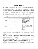
Page 47: ...ing the limited warranty period will be warranted under the terms of the limited warranty for a period not to exceed the remaining term of the original limited warranty or one year whichever is longer Parts Hearthstone will replace through an authorized dealer defective parts covered by the foregoing warranty at no charge Labor Within the first 1st year after the Purchase Date Hearthstone will pay...

Page 48: ...t gaskets baffles refractory materials ash grates and glass 4 Damage resulting from installation modification alteration repair or service of the appliance by any party other than an authorized Hearthstone dealer a Dealer or their designated representative or earthstone 5 Damage due to water or condensation due to installation of the appliance in a high moisture area 6 Damage due to installation o...

Page 49: ...ance for repair or to schedule a Dealer service call The Original Purchaser should refer to the Dealer Network search engine contained on earthstone s eb site www hearthstonestoves com if the original dealer is not available to find a earthstone dealer nearest to the Original Purchaser s location REMEDY The remedy for any breach of the foregoing warranties will consist of repair or replacement at ...

Reviews: