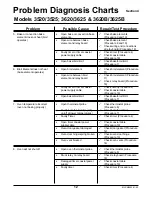
Problem
Possible Cause
Repair/Test Procedure
14
MLSM2003-01-03
Section 4
Problem Diagnosis Charts
Models 3520/3525; 3620/3625 & 3620B/3625B
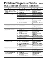
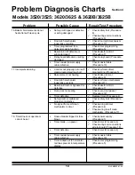
16.Bake & broil elements do not
heat after self clean cycle
•
Safety limit tripped or defective
or wiring damaged
•
Door latch mechanism
inoperative or wiring
•
Timer programmed for a
delayed cooking function
•
Bake/broil limit defective or
wiring damaged
•
Relay board defective or wiring
damaged
•
Timer coaxial power supply
cable defective
ü
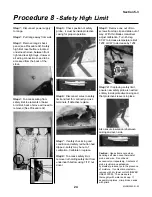
Check safety limit (Procedure
8)
ü
Check wiring and connections
(Procedure 8)
ü
Check door latch mechanism
(Procedure 17)
ü
Check timer programming
(Procedure 5)
ü
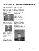
Check bake/broil limit
(Procedure 7)
ü
Check relay board (Procedure
18)
ü
Check coaxial cable
(Procedure 19)
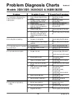
17.Incomplete cleaning
•
Controls not properly set or self
clean programmed too short
•
Bake element not heating
•
Door latch mechanism
inoperative or stuck
•
Bake/broil limit not bypassed or
defective
•
Oven door not sealing
•
Timer defective
•
Safety limit not calibrated
properly or defective
•
No signal from self clean
mechanism to timer
•
House breaker tripped or fuse
blown
•
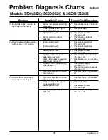
Timer blank – no power
•
Timer defective
•
Timer coaxial power supply
cable defective
•
Timer locked out (3 horizontal
red lines present in temperature
display
ü
Check power supply
(Procedure 1)
ü
Check timer (Procedure 4)
ü
Check wiring and connections
at relay board (Procedure 18)
ü
Check timer (Procedure 4)
ü
Check coaxial cable
(Procedure 19)
ü
Check timer programming
(Procedure 5)
18. Timer does not operate or
cannot be set
ü
Check self clean timer
programming (Procedure 5)
ü
Check bake element
(Procedure 9)
ü
Check self clean mechanism
(Procedure17)
ü
Check bake/broil limit
(Procedure 7)
ü
Check oven door gasket
(Procedure 12)
ü
Replace timer (Procedure 4)
ü
Check safety limit (Procedure
8)
ü
Check wiring at timer
(Procedure 4)
ü
Check wiring to self clean
mechanism (Procedure 17)
Summary of Contents for 3520
Page 4: ...4 MLSM2003 01 03 PAGE LEFT BLANK ...
Page 6: ...6 MLSM2003 01 03 PAGE LEFT BLANK ...
Page 10: ...Section 3 10 MLSM2003 01 03 PAGE LEFT BLANK ...
Page 57: ...Section 6 57 MLSM2003 01 03 Wiring Diagrams Models 3520 3525 ...
Page 58: ...Section 6 58 MLSM2003 01 03 Wiring Diagrams Models 3620 3625 ...


