Section 5-3
17
MLSM2003-01-03
Procedure 1
- Breakers & Fuses
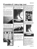
Step 1: Be sure all range controls
are turned off.
Step 2: To restore power, turn the
breaker switch to “OFF” position,
then back to “ON” (when a breaker
trips, the switch moves to an
intermediate position between the
“ON” and “OFF” positions)
Step 3: If breaker trips again, the
circuit is still overloaded.
Step 4: Fuse blocks utilize a
double pole fuse block with two
cartridge type fuses joined together
at the handle.
Step 5: Pull block out of panel
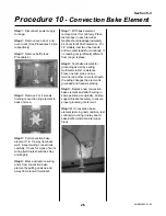
Step 6: Fuses can be checked
with ohnmmeter set at the lowest
resistance scale. Touch probes to
brass caps at each end. If no
continuity then replace with fuse
that meets local electrical codes
and is not larger than specified for
the range.
Step 7: Clip fuses firmly back on
panel (“ON” notation should appear
at the top of the block). Loose
connections can cause the fuse to
overheat.
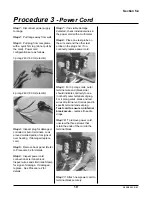
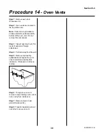
Step 8: Proper power readings on
receptacle can be tested with a
multimeter set to AC volts.
Step 9: With range unplugged,
place test probes as per diagrams.
Summary of Contents for 3520
Page 4: ...4 MLSM2003 01 03 PAGE LEFT BLANK ...
Page 6: ...6 MLSM2003 01 03 PAGE LEFT BLANK ...
Page 10: ...Section 3 10 MLSM2003 01 03 PAGE LEFT BLANK ...
Page 57: ...Section 6 57 MLSM2003 01 03 Wiring Diagrams Models 3520 3525 ...
Page 58: ...Section 6 58 MLSM2003 01 03 Wiring Diagrams Models 3620 3625 ...


