Section 5-3
19
MLSM2003-01-03
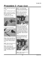
Procedure 3
- Power Cord
Step 1: Disconnect power supply
to range.
Step 2: Pull range away from wall.
Step 3: Pull plug from receptacle
with a quick firm tug (do not pull by
the cord). Power cord
configurations are as follows:
3 prong 240V; 60 Hz (electric)
4 prong 240V; 60 Hz (electric)
Step 4: Inspect plug for damaged,
corroded or burnt terminals. Look
around molded portion for signs of
over heating. If damaged replace
cord.
Step 5: Remove back panel (Refer
to Procedure 32 for details.
Step 6: Inspect power cord
connection at terminal block.
Inspect wires and strain relief clamp
for signs of damage. If damaged,
replace. See Procedure 2 for
details.
Step 7: If no visible damage
detected, check individual wires in
the power cord with a multimeter.
Step 8: Place one test probe on
the wire end and the other test
probe on the plug end. If no
continuity, replace power cord.
Step 9: For 3 prong cords, outer
terminal wire end (black side)
should indicate continuity to one
(not both) outer terminals of plug.
For 4 prong wires, black and red
wires at terminal end correspond to
specific terminal ends at plug.
Twist cord to ensure no internal
break occurs - replace if needle
drops.
Step 10: To remove power cord,
unscrew the three screws that
retain the ends of the cord to the
terminal block.
Step 11: Attach new power cord to
terminal block securely.
Summary of Contents for 3520
Page 4: ...4 MLSM2003 01 03 PAGE LEFT BLANK ...
Page 6: ...6 MLSM2003 01 03 PAGE LEFT BLANK ...
Page 10: ...Section 3 10 MLSM2003 01 03 PAGE LEFT BLANK ...
Page 57: ...Section 6 57 MLSM2003 01 03 Wiring Diagrams Models 3520 3525 ...
Page 58: ...Section 6 58 MLSM2003 01 03 Wiring Diagrams Models 3620 3625 ...


