Section 5-3
26
MLSM2003-01-03
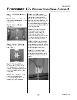
Step 1: Disconnect power supply
to range.
Step 2: Remove oven door and
oven racks (See Procedures 32 & 6
respectively)
Step 3: Remove baffle (see
Procedure 6).
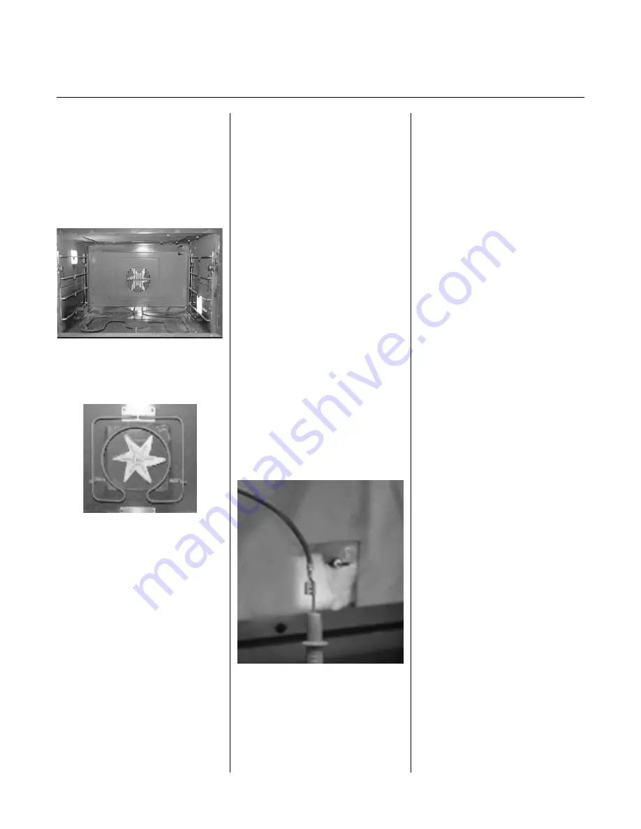
Step 4: Remove 2 or 4 screws
holding convection ring element to
back of stove.
Step 5: Pull convection bake
element 2” to 3” away from back
wall. Inspect wiring connections
carefully. Check for signs of burnt
wiring (terminals should be shiny
and bright).
Step 6: Mark and remove wiring
ends from convection bake
element by pulling ends up and
away from element terminals.
Step 7: With bake element
removed, test for continuity. Place
test probes on each terminal.
Needle should readapproximately
24 ohms for 2400W elements. For
36” models, test two inner leads
and two outer leads for continuity. If
no reading or significantly different
from range, replace.
Step 8: Test bake element for
grounding as well by setting
multimeter to Rx1 resistance.
Place one test probe on one
terminal and other on metal sheath.
If reading changes the element is
grounded and needs replacing.
Step 9: Replace new convection
bake element and attach wiring in
same position as originally. Fasten
support bracket securely to ensure
proper grounding of element.
Step 10: If convection bake
element tests in good condition, test
continuity in wiring to relay board,
bake/limit broil limit and terminal
block.
Procedure 10
- Convection Bake Element
Summary of Contents for 3520
Page 4: ...4 MLSM2003 01 03 PAGE LEFT BLANK ...
Page 6: ...6 MLSM2003 01 03 PAGE LEFT BLANK ...
Page 10: ...Section 3 10 MLSM2003 01 03 PAGE LEFT BLANK ...
Page 57: ...Section 6 57 MLSM2003 01 03 Wiring Diagrams Models 3520 3525 ...
Page 58: ...Section 6 58 MLSM2003 01 03 Wiring Diagrams Models 3620 3625 ...

