Section 5-3
36
MLSM2003-01-03
Procedure 19
- Timer Coaxial Cable
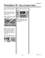
Step 1: Disconnect power supply
to range and pull unit away from
wall.
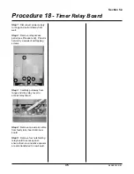
Step 2: Remove relay access
panel (see Procedure 18). Panel is
held in place by a series of self
tapping screws.
Step 3: Carefully pull out and drop
relay cover to access timer coaxial
power supply cable.
Step 4: Inspect cable for visible
damage and replace as needed. If
timer does not operate properly,
one of probable components is the
coaxial cable (other probable
components are the timer and the
relay board)
Step 5: Pull locking tabs away and
release cable from relay board.
Step 6: Release coaxial cable from
timer (see Procedure 4 for timer
access).
Step 7: Replace cable - please
cable is routed exactly as it was
and that it does not interfere with
any other wiring.
Summary of Contents for 3520
Page 4: ...4 MLSM2003 01 03 PAGE LEFT BLANK ...
Page 6: ...6 MLSM2003 01 03 PAGE LEFT BLANK ...
Page 10: ...Section 3 10 MLSM2003 01 03 PAGE LEFT BLANK ...
Page 57: ...Section 6 57 MLSM2003 01 03 Wiring Diagrams Models 3520 3525 ...
Page 58: ...Section 6 58 MLSM2003 01 03 Wiring Diagrams Models 3620 3625 ...


