Section 5-3
37
MLSM2003-01-03
Procedure 20
- Cooling Fan & Limit
Step 1: Disconnect power supply
to range and pull unit away from
wall.
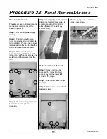
Step 2: Remove range’s back
panel (See procedure 32)
Step 3: Test continuity across
cooling fan’s terminals (pull black
and red wires). If fan test in good
condition, test wiring.
Step 4: To test wiring, place
multimeter probe on each wire and
test for continuity between fan and
terminal block and to fan limit.
Step 5: To access fan limit,
remove control panel (see
Procedure 34)
Step 6: If fan and wiring in good
condition, test fan limit for
continuity. Remove both red wires
and test across, limit should be
open and no reading taken across
terminals.
Step 7: If limit test in good
condition, inspect self clean
assembly microswitch (see
Procedure 17).
Step 8: If limit is faulty, replace.
remove wires to limit and transfer
red wires to new temperature limit.
Step 9: Remove one nut/bolt
holding limit to mounting bracket.
Note: Please ensure that red wires
do not run parallel with coaxial timer
cable or oven thermostat probe
when finished.
Summary of Contents for 3520
Page 4: ...4 MLSM2003 01 03 PAGE LEFT BLANK ...
Page 6: ...6 MLSM2003 01 03 PAGE LEFT BLANK ...
Page 10: ...Section 3 10 MLSM2003 01 03 PAGE LEFT BLANK ...
Page 57: ...Section 6 57 MLSM2003 01 03 Wiring Diagrams Models 3520 3525 ...
Page 58: ...Section 6 58 MLSM2003 01 03 Wiring Diagrams Models 3620 3625 ...


