Section 5-3
40
MLSM2003-01-03
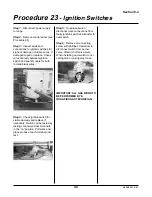
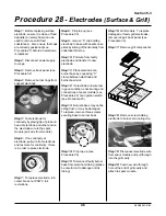
Step 1: Disconnect power supply
to range.
Step 2: Remove control panel (see
Procedure 34)
Step 3: Inspect wires and
connections to ignition switches for
signs of damage or broken wires. If
damaged repair or replace. Check
wire continuity between ignition
switch and spark module for both
red and black wires.
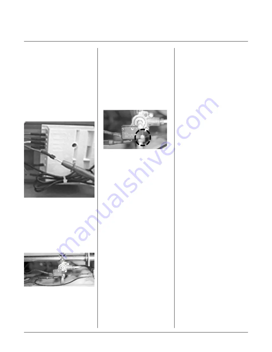
Step 4: Check ignition switch for
visible damage and replace if
necessary. Switch can be tested by
testing continuity across terminals
in the “on” position. Pull wires and
place probes at each terminal and
test.
Procedure 23
- Ignition Switches
Step 5: To replace switch
disconnect wire connections from
faulty ignition switch and transfer to
new switch.
Step 6: Remove one mounting
screw with phillips screwdriver to
disconnect switch from burner
valve. lift switch off valve stem.
When installing new switch do not
overtighten or casing may crack.
IMPORTANT: ALL GAS WORK TO
BE PERFORMED BY A
QUALIFIED GAS TECHNICIAN.
Summary of Contents for 3520
Page 4: ...4 MLSM2003 01 03 PAGE LEFT BLANK ...
Page 6: ...6 MLSM2003 01 03 PAGE LEFT BLANK ...
Page 10: ...Section 3 10 MLSM2003 01 03 PAGE LEFT BLANK ...
Page 57: ...Section 6 57 MLSM2003 01 03 Wiring Diagrams Models 3520 3525 ...
Page 58: ...Section 6 58 MLSM2003 01 03 Wiring Diagrams Models 3620 3625 ...

