Section 5-3
47
MLSM2003-01-03
Procedure 29
- Top Burner Valve
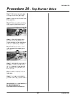
Step 1: Disconnect power supply
to range and shut off gas supply.
Step 2: Remove control panel (see
Procedure 34)
Step 3: Remove aluminum tubing
from defective valve with wrench.
Step 4: Remove ignition switch
(see Procedure 23). Wires can
remain on switch if new valve does
not have switch factory installed.
Step 5: Disconnect burner valve
from manifold by removing two 8
mm nuts.
Step 6: Install new burner valve to
manifold - ensure new valve has
the “o” ring gasket to seal against
the manifold. If not, transfer seal
from old valve.
Step 7: Attach aluminum tube to
new valve.
Step 8: Turn gas on and test for
gas leaks with soapy water solution.
IMPORTANT: ALL GAS WORK TO
BE PERFORMED BY A
QUALIFIED GAS TECHNICIAN.
Summary of Contents for 3520
Page 4: ...4 MLSM2003 01 03 PAGE LEFT BLANK ...
Page 6: ...6 MLSM2003 01 03 PAGE LEFT BLANK ...
Page 10: ...Section 3 10 MLSM2003 01 03 PAGE LEFT BLANK ...
Page 57: ...Section 6 57 MLSM2003 01 03 Wiring Diagrams Models 3520 3525 ...
Page 58: ...Section 6 58 MLSM2003 01 03 Wiring Diagrams Models 3620 3625 ...


