background image

14

Installation

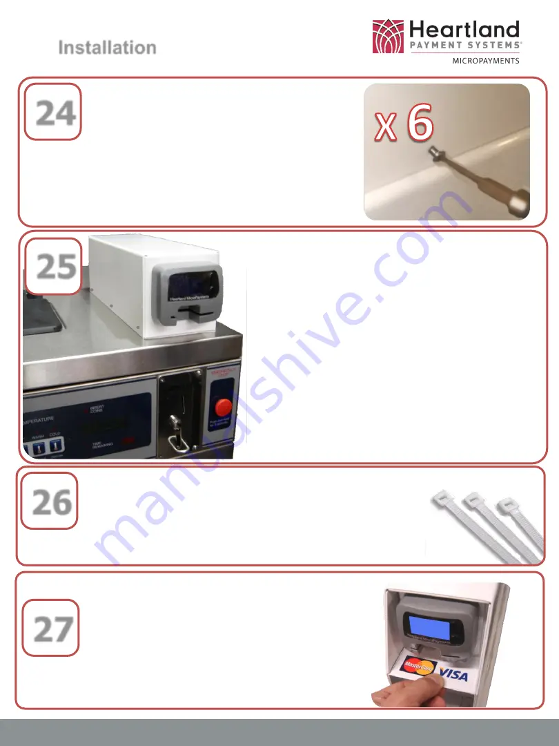
24

www.heartlandMicroPayments.com

Install the six (6) 6-32 x 
3/8"Button Torx screws  to 
secure the Side Car top cover 
to the bottom panel.   There 
are three (3) per side.

25

Finished 

assembly.

26

Using zip-ties, secure all wiring harnesses to 
prevent pinching, wire-strain, and chafing.

27

Apply the self-adhesive sticker 
that displays the accepted card 
brands (supplied) in a clearly 
visible location .

Summary of Contents for WaveRider

Page 1: ...www heartlandMicroPayments com 2115 Chapman Road Suite 159 Chattanooga TN 37421 800 332 4835 WaveRider Installation Single Machine Side Car Enclosure Coin Card Pulse Mode TOP OF MACHINE MOUNTING ...

Page 2: ...er installation process following Dexter model numbers If you cannot locate the model number of the machine you require in the lists above please contact MicroPayments Customer Service at Tel 800 332 4835 Press 2 Washers T 300 WCAD20KCS T 400 WCAD30KCS T 600 WCAD40KCS T 900 WCAD60KCS T 1200 WCAD80KCS ...

Page 3: ... WLAU NNNNNN WaveReader WaveReader 1 Required Tools T 20 Pin in Star Torx Driver Phillips Head Screwdriver med magnetic tip is helpful Electric Drill Heavy Duty 9 32 Drill Bit 7 8 Drill Bit or Step Drill bit to match 11 32 Nut Driver or Socket Ratchet If you cannot locate and or identify any of the components listed above please contact MicroPayments Customer Service at 800 332 4835 then press 2 ...

Page 4: ... 1 AYS 050 6 012 Stuffed Dexter Coin Interface Board 2 2a 1 AYS 050 6 019 Cable Dexter Pulse for WR Coin 2 part 3 1 AYS 168110 110 VAC Transformer Interface Harness 1 2 2a If you cannot locate and or identify any of the components listed above please contact MicroPayments Customer Service at 800 332 4835 then press 2 3 ...

Page 5: ...32 4835 then press 2 KIT 050 6 040 Side Car Enclosure Kit Surface Mount Item Qty Part Number Description 1 1 MFP 050 6 A040 Side Car Surface Mount Bottom 2 1 MFP 050 6 032 011 Side Car Cover 3 6 SRW 632X 375BTSS Screw 6 32 x 3 8 Button Torx Socket 4 4 WAS 1 4 20L Washer 1 4 20 locking 5 4 NUT 4X20SH Nut 20 Steel Hex 6 4 SRW 632X 188PPL Screw 6 32 x 3 16 Pan Head Phil locking ...

Page 6: ...d line it up as shown Mark the location of the four 4 bottom mounting posts and the center hole for drilling Preparation Disconnect the laundry machine from all power sources before performing any of the following steps www heartlandMicroPayments com Completely remove the top cover of the washing machine and drill the marked holes to size Mount the bottom of the side car cover to the machine top a...

Page 7: ...AC transformer supplied with the WaveReader installation kit 4 Connect the two spade lugs from the primary side of the transformer to the 2 and 5 lugs of the power distribution bar as shown Locate the Dexter Interface Board supplied with the installation kit 5 ...

Page 8: ...Connect the white bundled Dexter display cable to the mating To Display connector on the Interface Board as shown 6 Disconnect the exiting coin drop connectors from the control board 7 Disconnect the white bundled display cable from the control board ...

Page 9: ... drop cables to their mating connectors Coin Drop Coin Drop on the Interface Board as shown Locate the WaveRider Dexter display harness that was supplied with the installation kit Connect one end they are the same to the From Controller connector on the Interface Board as shown ...

Page 10: ... end to the Dexter control board as shown 13 Locate the WaveRider Dexter interface harness supplied with the installation kit It has multiple ends as shown 14 Connect the 10 Pin black connector of the WaveReader harness to the Cable In connector of the Interface Board ...

Page 11: ... the coin drop was disconnected from 17 Connect the two spade lugs of the secondary side thin wires coming from the supplied transformer to their mating ends on the machine interface harness Connect the 4 position white connector it will have one green wire of the WaveReader harness to the Dexter control board at the same place that the coin drop was disconnected from ...

Page 12: ...Locate the top cover of the Side Car Kit Insert the WaveReader into the cover as shown and position cover to align the holes with those on the back of the WaveReader 19 18 Securely mount the Interface Board in a suitable location as shown Mounting holes are provided for screws Replace the machine s top cover with the side car bottom attached Do not secure the top cover ...

Page 13: ...upplied with the Side Car Kit 22 Connect the large free end J1 of the WaveReader harness that was pulled through the hole to the connector on the back of the reader Position the top Side Car cover so that the two 2 retaining pins at the back edge line up with their mating holes in the bottom cover Tap the top cover down so that the pins are fully inserted ...

Page 14: ... secure the Side Car top cover to the bottom panel There are three 3 per side 25 Finished assembly 26 Using zip ties secure all wiring harnesses to prevent pinching wire strain and chafing 27 Apply the self adhesive sticker that displays the accepted card brands supplied in a clearly visible location ...

Page 15: ...into the coin drop 2 Verify the machine has recognized the coin and deducted 25c from the total price 3 Swipe a card wait for the transaction to be approved and then press START on the WaveReader 4 Verify that machine has received all of the funds required for a cycle and it is ready to start Note the card will be charged a full cycle price You are only verifying that the machine is receiving puls...

Reviews: