58
Heat & Glo • SL-750TRS-IPI-E, SL-550TRS-IPI-E, SL-350TRS-IPI • 2120-901 Rev. U • 11/13
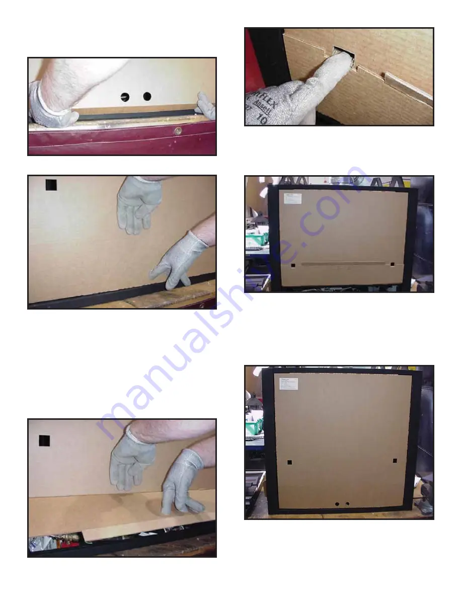
Step 5. Fold bottom
fl
ap along score line as indicated in
Figure 13.6 and tuck into valve access area of appliance.
Splatter guard should
fi
t securely on front of unit.
Figure 13.6
Once plumbing and wiring are complete on the
fi
replace,
the lower access panel may be closed until the time that the
splatter guard must be removed for
fi
ring the appliance.
Figure 13.7
Step 6. To open lower access panel of splatter guard,
place one hand above score line and place two
fi
ngers
from other hand in the round holes on the front of the
splatter guard. See Figure 13.7. Pull out and fold up
the panel as shown in Figure 13.8. Disengage the tabs
on left and right bottom of splatter guard and
fi
t them
into the square holes. The tabs are now inside the front
of the splatter guard; carefully bend them down. See
Figure 13.9.
Figure 13.9
Figure 13.8
To Close the Lower Access Panel:
Carefully disengage the tabs from the square holes and
bend the access panel to its original position. Bend the
center bottom
fl
ap and insert it into the bottom of the ap-
pliance.
To Remove the Splatter Guard:
Carefully grab splatter guard on or near the vertical center
on the left and right sides. Pull outward gently, but
fi
rmly,
taking care not to tear or remove the inserted tabs.
Figure 13.11
Figure 13.10


