Heat & Glo • SL-36-Ultimate • 2141-900 Rev. i • 5/11
40
F. Glass Assembly
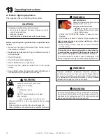
Handle glass doors with care.
• Inspect the gasket to ensure it is undamaged.
• Inspect the glass for cracks, chips or scratches.
• Do NOT strike, slam or scratch glass.
• Do NOT operate appliance with glass door removed,
cracked, broken or scratched.
• Replace glass door assembly as a complete appliance.
WARNING
Removing Glass Assembly
Unlatch the two latches at the bottom of the glass door.
Carefully pull the bottom of the door away from the unit
and lower the top tabs on the door out of the top latches
as tension is relieved.
Replacing Glass Assembly
Angle the top of the glass door in toward the appliance and
insert the tabs on top of the glass frame into the top latches.
Rotate the bottom of the glass door toward the fi rebox with
slight upward pressure. Latch the bottom spring latches
securely onto the bottom glass door tabs.
G. Burner Removal (Only for Servicing)
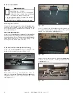
Loosen the shutter adjustment wing nut and move the
shutter to the closed position (see Figure 12.10).
Figure 12.10
Wing nut
Remove the air baffl e by removing the two screws at-
taching it to the burner. Remove the two screws holding
the pilot and the one screw from the front of the burner
(see Figure 12.11).
Figure 12.11
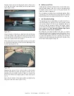
Figure 12.12
Slide the burner to the right while angling the right side of
the burner forward until the burner is free of the shutter
sleeve, then lift out burner (see Figure 12.12).
Using a 3/8” nut driver or wrench, remove the natural gas
orifi ce and replace it with the LP orifi ce provided in this kit
(see Figure 12.13).
Orifi ce Holder
Shutter Sleeve
Burner Neck
Open Closed
Figure 12.13

