background image

27

Heat & Glo  •  SLR-X-AU-L Owner’s Manual   •  2653-981 Rev. B  •  5/20  

With proper installation, operation, and maintenance your gas appliance will provide years of trouble-free service.  If you do 

experience a problem, this troubleshooting guide will assist a qualified service technician in the diagnosis of a problem and 

the corrective action to be taken. This troubleshooting guide can only be used by a qualified service technician.  Contact 

your dealer to arrange a service call by a qualified service technician.

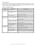
B. Troubleshooting

IntelliFire™ Plus Ignition System

Symptom

Possible Cause

Corrective Action

1. Pilot won’t light. 

The ignitor/module 

makes noise, but no 

spark.

A.  Incorrect wiring.

Verify “S” wire (white) for sensor and “I” wire (orange) for ignitor are 

connected to correct terminals on module and pilot assembly.

B.  Loose connections or electrical 

shorts in the wiring.

Verify no loose connections or electrical shorts in wiring from mod

-

ule to pilot assembly. Verify connections underneath pilot assembly 

are tight; also verify igniter and flame sense wires are not grounding 

out to metal chassis, pilot burner, pilot enclosure, mesh screen if 

present, or any other metal object. 

C.  Ignitor gap is too large.

Verify gap of igniter to right side of pilot hood. The gap should be 

approximately .17 in. or 1/8 in. (3 mm).

2. Pilot won’t light, 

there is no noise or 

spark.

A.  No power, transformer installed 

incorrectly, or depleted batteries.

Verify that transformer is installed and plugged into module. Check 

voltage of transformer at connection to module. Acceptable read

-

ings of a good transformer are between 6.4 and 6.6 volts DC.  Bat

-

tery power supply voltage must be at least 4 volts.  If less than 4 

volts, replace batteries.

B.  A shorted or loose connection in 

wiring configuration or wiring har

-

ness.

Remove  and  reinstall  the  wiring  harness  that  plugs  into  module. 

Verify there is a tight fit. Verify pilot assembly wiring to module. Re

-

move and verify continuity of each wire in wiring harness.  Replace 

any damaged components.

C.  Improper wall switch wiring.

Verify that 220/240 VAC service power is “ON” to appliance.

D.  Module not grounded.

Verify black ground wire from module wire harness is grounded to 

metal chassis of appliance.

3. Pilot sparks, but 

Pilot will not light.

A.  Gas supply.

Verify  that  incoming  gas  line  ball  valve  is  “open”.  Verify  that  inlet 

pressure reading is within acceptable limits.

B.  Ignitor gap is too large.

Verify gap of igniter to right side of pilot hood. The gap should be 

approximately .17 in. or 1/8 in. (3 mm).

C.  Module is not grounded.

Verify module is securely grounded to metal chassis of appliance.

D.  Pilot valve solenoid. 

Verify that 1.5 to 1.8 VDC is supplied to pilot solenoid from module.  

If below 1.5 volts, replace module.  If 1.5 volts or greater, replace 

valve.

Summary of Contents for SLR-X-AU-L

Page 1: ...ier s instructions If you cannot reach your gas supplier call the fire department Installation and service must be performed by a qualified installer service agency or the gas supplier WARNING FIRE OR EXPLOSION HAZARD Failure to follow safety warnings exactly could result in serious injury death or property damage DANGER HOT GLASS WILL CAUSE BURNS DO NOT TOUCH GLASS UNTIL COOLED NEVER ALLOW CHILDR...

Page 2: ...th Home Technologies 7571 215th Street West Lakeville MN 55044 ASXXXX Certification Nº GMKXXXXX Injector Size DMS mm Inlet Gas Pressure kPa Outlet Manifold Gas Pressure kPa Maximum Nominal Gas Consumption MJ h Electrical Rating 240V 50hz 1A This unit is designed to be recessed into framed construction TO BE INSTALLED ON WOOD FLOORING OR NON COMBUSTIBLE FLOORING See installation manual for details ...

Page 3: ...atulations 2 B Limited Lifetime Warranty 4 2 Product Specific Information A Appliance Certification 7 B Gas Pressure Requirements 7 C Glass Specifications 7 3 Important Safety and Operating Information A Appliance Safety 8 B General Operating Parts 9 C Fuel Specifications 9 D Good Faith Wall Surface TV Guidelines 9 E Before Lighting Appliance 11 F Lighting Instructions IPI 12 G Appliance Break In ...

Page 4: ...ime periods reflect the minimum expected useful lives of the designated components under normal operating conditions 2000 645G 5 20 Page 1 of 3 Warranty Period HHT Manufactured Appliances and Venting Parts Labor Gas Pellet Wood Electric Venting Components Covered 1 year X X X X X All parts including handles external enameled components and other material except as covered by Conditions Exclusions ...

Page 5: ... by HHT in writing and or 9 interrup tions or fluctuations of electrical power supply to the appliance 2000 645G 5 20 Page 2 of 3 Warranty Period HHT Manufactured Appliances and Venting Parts Labor Gas Pellet Wood Electric Venting Components Covered 6 years 3 years X Catalyst Limitations Listed 7 years 3 years X X Manifold Tubes HHT Chimney and Termination 10 years 1 year X Burners Logs and Refrac...

Page 6: ...ater or weather damage which is the result of but not limited to improper chimney or venting installation HOW TO CLAIM To make a claim against this warranty contact your local distributor during regular business hours See addresses below for a dealer nearest you Vic Pty Ltd ACN 005 872 159 Jetmaster Additional service fees may apply if you are seeking warranty service from a dealer other than the ...

Page 7: ...m3 h 134 m3 h 111 m3 h Maximum Gas Consumption 31 65 MJ h 27 43 MJ h 25 30 MJ h Burner Injector 37 DMS 2 64 mm 53 DMS 1 51 mm 057 DMS 1 45 mm Pilot Injector Ø 023 584 mm Ø 014 356 mm Ø 010 254 mm Gas types only through field conversions THE GUARD IS FITTED TO THIS APPLIANCE TO REDUCE THE RISK OF FIRE OR INJURY FROM BURNS AND NO PART OF IT SHOULD PERMANENTLY BE REMOVED FOR PROTEC TION OF YOUNG CHIL...

Page 8: ...ach children to NEVER touch the fireplace Consider not using the fireplace when children will be present Contact your dealer for more information or visit www hpba org Product Info Fireplace Stove Heater Glass Fronts Safety To prevent unintended operation when not using your fire place for an extended period of time summer months vacations trips etc Remove batteries from remote controls Turn the O...

Page 9: ...ve are taken with a temperature measuring probe as prescribed by the test standard used for appliance certification Temperatures on walls or mantels taken with an infrared thermometer may yield increased temperatures of up to 30 F 17 C degrees or more depending on the thermometer settings and material characteristics being measured Use appropriate finishing materials that are able to withstand the...

Page 10: ...e manufacturers maximum allowable opera ng temperatures iden fied in the TV s technical specifica ons Contact the TV s manufacturer directly if you cannot locate this informa on or have ques ons regarding the informa on 3 Mantel height and depth must conform to mantle requirements specified in the appliance installa on manual 4 C dimension taken from the top of the hood or appliance opening 5 Sugges ...

Page 11: ... removed from inside and or underneath the firebox Review proper placement of logs ember material and or other decorative materials Check the wiring Check the air shutter adjustment Ensure that there are no gas leaks Ensure that the glass is sealed and in the proper position and that the integral barrier is in place WARNING Risk of Fire or Asphyxiation DO NOT op erate fireplace with fixed glass as...

Page 12: ... Hot while in operation DO NOT touch Keep children clothing furniture gasoline and other liquids having flammable vapors away DO NOT operate the appliance with fixed glass assembly removed cracked or broken Replacement of the fixed glass assembly should be done by a licensed or qualified service person Immediately call your gas supplier from a neighbor s phone Follow the gas sup plier s instructions I...

Page 13: ...the finishing materials around it The fireplace should be run three to four hours continuously on high Turn the fireplace off and allow it to cool completely Remove fixed glass assembly See Section 4 B Clean fixed glass assembly See Section 4 Replace the fixed glass assembly and run continuously on high an additional 12 hours Note Some IPI systems have a safety feature that automatically shuts dow...

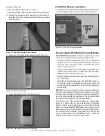
Page 14: ...itch Toggle the switch as you would under normal circumstances Wireless Remote Remote receiver is integrated into the ignition module Use the remote to turn the appliance on To preserve battery life do not use the HI LO flame or THERMOSTAT options Ignition Module Locate the ignition module in the control cavity See Figure 3 5 Slide the ON REMOTE OFF switch to the ON position To Return to Operation...

Page 15: ...with battery backup REMOTE Position Appliance will initiate commands from an optional wired wall switch and or the wireless remote RC300AU 2 If using a wired wall switch with the module in REMOTE mode the flame output can be adjusted with the HI LO selector switch on the module See Figure 3 6 Note that the flame HI LO selector switch will become inactive once an remote control RC300AU is programme...

Page 16: ...damaged Do not modify disassemble or substitute any of the com ponents included with this kit Installation of this unit must be done by a qualified service technician Placement of this remote control may affect performance An assessment of the space should be done prior to in stallation for optimum performance Determine Location Determine the location for the remote control The selected location s...

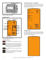
Page 17: ...ol module will beep once and LED will blink green for 10 seconds While the LED is blinking press the POWER button on the remote control A double beep will come out of the control module to indicate that it has been programmed successfully NOTICE Up to three remote controls can be programmed into the control module Simply press a button on the other remote controls during the 10 second programming ...

Page 18: ...ple Flame Height will not be displayed when the remote status is OFF Use the SELECT button to select the current feature Use the UP and DOWN arrows to toggle through the menu functions and value selec tions in the submenus Idle When Remote is in ON Mode The remote control will go into an idle mode if no but tons are pressed within 5 seconds Press any button to resume full functionality In idle mod...

Page 19: ... OFF mode when the flame is off When the fireplace is turned back ON the AUX1 and AUX2 settings will be restored to the previous setting AUX1 Function Unit dependent Function Press the MENU button to activate the menu Using the UP and DOWN arrows highlight the AUX1 icon and press SELECT Use the UP and DOWN arrows to adjust the AUX1 output then press SELECT The AUX1 function can be adjusted to 4 di...

Page 20: ...Control module will not take commands from remote control Control module is not in REMOTE mode Ensure module switch is set to REMOTE Control module and remote control are not programmed to each other The control module will beep when it successfully receives a command If it does not beep clear module memory and repro gram the remote control Control module is un plugged In case of power outage back...

Page 21: ... Heat Zone 240V Kit is installed by a qualified service technician during the appliance installa tion process follow the instruction supplied with the kit for operation K Heat Management Standard Fan A standard fan has been supplied with this product and the operation is controlled by the RC300 HNG AU remote ...

Page 22: ...bly See Figure 4 1 Clean glass with a non abrasive commercially available cleaner Light deposits Use a soft cloth with soap and water Heavy deposits Use commercial fireplace glass cleaner consult with your dealer Carefully set fixed glass assembly in place on fireplace Hold glass in place with one hand and secure glass latches with the other hand B Maintenance Tasks Homeowner The following tasks m...

Page 23: ...tion on the glass assembly Use one hand to support the glass at all times 3 Verify that the top two glass latches are engaged by vi sually verifying that glass latches have engaged both left and right tabs on the glass frame 4 Verify the bottom two glass latches have engaged the glass frame tabs by grasping the bottom of the glass frame assembly and pulling the glass frame assembly away from the f...

Page 24: ...cian Tools needed Protective gloves vacuum cleaner whisk broom flashlight voltmeter indexed drill bit set and a manometer Verify burner is properly secured and aligned with pilot or igniter Clean off burner top inspect for plugged ports corrosion or deterioration Replace burner if necessary Decorative Fronts Surrounds Frequency Annually By Homeowner Tools needed Protective gloves stable work surfa...

Page 25: ...rifice size is correct See Service Parts List for proper orifice sizing Verify manifold and inlet pressures Adjust regulator as required Inspect pilot flame pattern and strength See Figure 4 2 for proper pilot flame pattern Clean or replace orifice spud as necessary Inspect IPI flame sensing rod for soot corrosion and deterioration Polish with fine steel wool or replace as required Verify that the...

Page 26: ...n abrasive cleaner such as gas fireplace glass cleaner may be necessary See your dealer Metallic noise Noise is caused by metal expanding and contracting as it heats up and cools down similar to the sound produced by a furnace or heating duct This noise does not affect the operation or longevity of the fireplace Is it normal to see the pilot flame burn continually In an intermittent pilot ignition...

Page 27: ... 17 in or 1 8 in 3 mm 2 Pilot won t light there is no noise or spark A No power transformer installed incorrectly or depleted batteries Verify that transformer is installed and plugged into module Check voltage of transformer at connection to module Acceptable read ings of a good transformer are between 6 4 and 6 6 volts DC Bat tery power supply voltage must be at least 4 volts If less than 4 volt...

Page 28: ... Verify continuity with a multi meter with ohms set at lowest range Replace pilot if any damage is detected 5 Appliance lights and runs for a few minutes and then shuts down and or appliance cycles on and off A A shorted or loose connection in flame sensing rod Verify all connections to wiring diagram in manual Verify connections underneath pilot assembly are tight Verify flame sense or igniter wi...

Page 29: ...rate your fireplace For safety Install a switch lock or a wall remote control with child protection lockout feature Keep remote controls out of reach of children See your dealer if you have questions Optional Heat Zone 240V Gas Kit After a qualified service technician has installed the Heat Zone 240V Gas Kit follow the instruction supplied with the kit for operation Contact your dealer if you have...

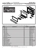
Page 30: ...RT NUMBER 1 Log 1 SRV571 705 2 Log 2 SRV2491 703 3 Log 3 SRV2081 172 4 Log 4 SRV330 704 5 Log 5 SRV2111 701 6 Log 6 SRV2111 702 Lava Rock 4021 297 Mineral Wool 050 721 7 Non Comb Ledge 2493 104 8 Top Fill 2493 135 9 Non Comb Assembly 2493 079 10 Base Pan 2491 111 11 Burner Assembly 2491 009 12 Valve Assembly See Following Page 13 Glass Assembly GLA SLR X AU 14 Lower Panel 2493 103 15 Heat Shield S...

Page 31: ...ilot Assembly N 2106 169 Pilot Assembly P ULPG 2106 170 12 3 Burner Support 1 Set 2491 169 12 4 Bulkhead W Flex Tube 4021 428 12 5 Valve Bracket 2491 153 12 6 Flex Ball Valve Assembly SRV302 320 12 7 Valve N 2166 302 Valve P ULPG 2166 303 12 8 Male Connector Pkg of 5 303 315 5 12 9 Module Gray 2166 306 12 10 AUX300 CE 2166 340 12 11 Wiring Harness 2166 304 12 12 Power Cord Assembly 2222 037 12 13 ...

Page 32: ...DESCRIPTION COMMENTS PART NUMBER Exhaust Restrictor 530 299 Fan Deflector Brackets includes two brackets 2493 241 Gasket Assembly 2113 080 Contains burner neck shutter bracket vent seal cap valve plate and air passage gaskets Glass Clip XS Assembly Qty 2 req 2155 045 Glass Clip Assembly Pre Set Qty 2 req 2155 046 Touch Up Paint TUP GBK 12 Wall Switch Kit WSK 21 W Remote Assembly REM300 HNG AU Conv...

Page 33: ...____________________________________________________ ________________________________________________________________________________ ________________________________________________________________________________ ________________________________________________________________________________ ________________________________________________________________________________ DO NOT DISCARD THIS MAN...

Reviews: