background image

Page 11 of 16

18-December-2008

92-42810-GLDH

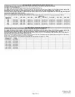
90% GAS FURNACE - ORIFICE SELECTION CHART - NATURAL GAS

CAUTION: Selection of the correct Natural Gas Orifice requires the following information for the specific installation:
1) Altitude in of the installation (ft.).
2) Average energy content of the Natural Gas fuel from the local supplier (BTU/cu. ft.).
For detailed information and instructions for Orifice selection, see the Gas Furnace LP Conversion Kit Index 92-21519-59 and the latest edition of the
National Fuel Gas Code Handbook, or the National Standard of Canada, Natural Gas and Propane Installation Code, CAN B149.1.
CAUTION: This information is provided for replacement purposes only. Conversion for operation at High Altitude must be done using the kit specified
on the product specification sheet for the unit.
NOTE: This Orifice sizing chart is based on 15,000 BTU/HR per burner.
NOTE: Factory installed orifices are calculated and sized based on a Natural Gas heating value of 1075 BTU/cu. ft. and an elevation of 0 - 2000 ft.
 

Elevation (ft.)

Energy Value

(BTU/cu. ft.)

0 - 1999

2000 - 2999

3000 - 3999

4000 - 4999

5000 - 5999

6000 - 6999

7000 - 7999

8000 - 8999

850

62-22175-47

62-22175-48

62-22175-48

62-22175-49

62-22175-49

62-22175-49

62-22175-50

62-22175-50

900

62-22175-48

62-22175-49

62-22175-49

62-22175-49

62-22175-50

62-22175-50

62-22175-50

62-22175-51

975

62-22175-49

62-22175-50

62-22175-50

62-22175-50

62-22175-51

62-22175-51

62-22175-51

62-22175-52

1075

62-22175-50

62-22175-51

62-22175-51

62-22175-51

62-22175-51

62-22175-52

62-22175-52

62-22175-52

1170

62-22175-51

62-22175-51

62-22175-52

62-22175-52

62-22175-52

62-22175-53

62-22175-53

62-22175-53


90% GAS FURNACE - ORIFICE SELECTION CHART - LP

CAUTION: Selection of the correct LP Orifice requires the altitude of the specific installation (ft.).
For detailed information and instructions for Orifice selection, see the Gas Furnace LP Conversion Kit Index 92-21519-59 and the latest edition of the
National Fuel Gas Code Handbook (NFG), or the National Standard of Canada, Natural Gas and Propane Installation Code, CAN B149.1.
CAUTION: This information is provided for replacement purposes only. Conversion to LP or for operation at High Altitude should be done using the
kit(s) specified on the product specification sheet for the unit.
NOTE: This Orifice sizing chart is based on 15,000 BTU/HR per burner. Also, the chart is developed using the specified pressure setting of 10 in. water column
instead of the 11.0 in water column used by the NFG and CANB149.1.
NOTE: Orifices supplied in the LP Conversion Kit are calculated and sized based on an altitude of 0 - 2000 ft.

Elevation (ft.)

Orifice


0 to 2000 ft.

62-22175-91


2001 to 3000

62-22175-91


3001 to 4000

62-22175-90


4001 to 5000

62-22175-58


5001 to 6000

62-22175-59


6001 to 7000

62-22175-60


7001 to 8000

62-22175-62


8001 to 9000

62-22175-63


9001 to 1000

62-22175-64


Summary of Contents for GLDH Series

Page 1: ...GLDH Parts List 18 December 2008 This parts list is current as of the above revision date Form Number 92 42810 GLDH ...

Page 2: ...r Burner Group Page 9 Gas Controls Page 10 Burner Assembly Page 15 Notes Page 16 Horizontal Installation Parts Page 13 Blower Assembly Page 14 Panels Miscellaneous 09 12 Page 5 Panels Miscellaneous 04 07 Page 4 Model Explanation Page 3 Blower Group Page 8 Electrical Group Page 7 Parts Bag Page 6 Parts Numbers Drawings Photographs ...

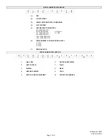
Page 3: ...U HR 60 60 000 BTU HR E Electric 75 75 000 BTU HR N NOX 90 90 000 BTU HR 105 105 000 BTU HR 120 120 000 BTU HR 6 DRIVE NOMINAL COOLING REVISION LEVEL 3 3 Ton 4 4 Ton 5 5 Ton 7 REVISION LEVEL SERIAL NUMBER EXPLANATION G Y 5 D 7 0 2 F 3 1 0 7 9 9 9 9 1 2 3 4 5 6 7 8 9 10 1 GAS CODE 6 MOTOR HORSEPOWER 2 LIMIT CONTROL 7 PLANT 3 BLOWER 8 WEEK 4 HEATING ELEMENT 9 YEAR 5 SPECIAL AREA REQUIREMENT 10 PRODU...

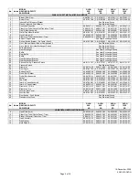
Page 4: ...ilicone Tubing Pressure Switch AE 61737 27 AE 61737 27 AE 61737 27 AE 61737 27 26 Pressure Switch See Electrical Group 27 Grommet 56 22114 06 56 22114 06 56 22114 06 56 22114 06 28 Door Angle AS 67847 01 AS 67847 01 AS 67847 01 AS 67847 02 29 Button Plug 2 45 22980 08 45 22980 08 45 22980 08 45 22980 08 30 Outlet Pipe Gasket 68 24022 02 68 24022 02 68 24022 02 68 24022 02 31 Outlet Pipe Assembly 6...

Page 5: ...ilicone Tubing Pressure Switch AE 61737 27 AE 61737 27 AE 61737 27 AE 61737 27 26 Pressure Switch See Electrical Group 27 Grommet 56 22114 06 56 22114 06 56 22114 06 56 22114 06 28 Door Angle AS 67847 02 AS 67847 02 AS 67847 02 AS 67847 03 29 Button Plug 2 45 22980 08 45 22980 08 45 22980 08 45 22980 08 30 Outlet Pipe Gasket 68 24022 02 68 24022 02 68 24022 02 68 24022 02 31 Outlet Pipe Assembly 6...

Page 6: ...G Complete Parts Bag Assembly AS 100717 03 1 2 in PVC Pipe 4 in 68 22024 04 1 2 in Tee 68 21980 02 PVC Vane 68 23473 01 PVC Wind Vane 2 1 2 in 68 24049 01 Drain Tube 6 3 4 in 68 24026 04 Elbow 68 24121 01 9 Hose Clamps 2 64 22043 03 12 1 Trap Assembly 68 24120 02 13 Trap Gasket 68 24123 01 14 Hole Plug 2 45 24125 01 ...

Page 7: ...22860 01 47 22860 02 58 Stk Limit Manual Reset Burner Compartment 47 22861 02 1 47 22861 02 1 47 22861 02 2 47 22861 02 2 No Notes MODEL HEATING CAPACITY VARIATIONS GLDH 90E 4B GLDH 90E 5B GLDH 105E 5B GLDH 120E 5B ELECTRICAL GROUP 3 Induced Draft Blower w Gasket 70 24033 01 70 24033 01 70 24033 01 70 24033 01 4 Gasket Induced Draft Blower 68 24016 01 68 24016 01 68 24016 01 68 24016 01 17 Stk Lim...

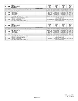
Page 8: ... Blower Motor 43 100509 42 43 100509 42 43 100509 42 43 21298 43 54 Limit Heat Assisted Blower Housing See Electrical Group No Notes MODEL HEATING CAPACITY VARIATIONS GLDH 90E 4B GLDH 90E 5B GLDH 105E 5B GLDH 120E 5B BLOWER GROUP 44 Stk Blower Assembly Includes items 45 48 and 53 AS 61697 96 AS 61697 97 AS 61697 97 AS 61697 99 45 Motor Mount Leg 4 AE 61698 02 AE 61698 02 AE 61698 02 AE 61698 02 46...

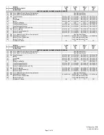
Page 9: ...ifice Natural Gas See Orifice Selection Chart 60 Burner Orifice LP See Orifice Selection Chart Number of Orifices 3 4 5 5 No Notes MODEL HEATING CAPACITY VARIATIONS GLDH 90E 4B GLDH 90E 5B GLDH 105E 5B GLDH 120E 5B HEAT EXCHANGER BURNER MANIFOLD GROUP 17 Stk Limit Manual Reset Burner Compartment See Electrical Group 18 Stk Limit Main Limit Heat Exchanger Panel See Electrical Group 19 Stk Heat Exch...

Page 10: ...25338 01 62 24140 04 62 24140 04 61 Stk Gas Valve Natural Gas 60 100394 02 60 22866 01 60 23490 01 61 Stk 1 Gas Valve LP See Note 1 See Note 1 See Note 1 63 Stk Ignitor 62 24141 04 62 24141 04 62 24141 04 64 Ignitor Bracket AE 61885 02 AE 61885 02 AE 61885 02 65 Stk Flame Sensor 62 23543 01 62 23543 01 62 23543 01 Stk LP Conversion Kit FP 02 FP 02 FP 02 ...

Page 11: ... 62 22175 51 975 62 22175 49 62 22175 50 62 22175 50 62 22175 50 62 22175 51 62 22175 51 62 22175 51 62 22175 52 1075 62 22175 50 62 22175 51 62 22175 51 62 22175 51 62 22175 51 62 22175 52 62 22175 52 62 22175 52 1170 62 22175 51 62 22175 51 62 22175 52 62 22175 52 62 22175 52 62 22175 53 62 22175 53 62 22175 53 90 GAS FURNACE ORIFICE SELECTION CHART LP CAUTION Selection of the correct LP Orifice...

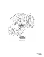
Page 12: ...Page 12 of 16 18 December 2008 92 42810 GLDH Exploded View ...

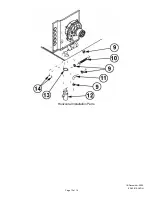
Page 13: ...Page 13 of 16 18 December 2008 92 42810 GLDH Horizontal Installation Parts ...

Page 14: ...Page 14 of 16 18 December 2008 92 42810 GLDH Blower Assembly ...

Page 15: ...Page 15 of 16 18 December 2008 92 42810 GLDH Burner Assembly ...

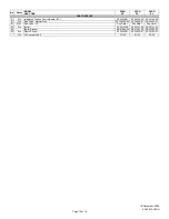
Page 16: ...NOTES 1900 Wellworth Jackson MI 49203 Stk It is recommended that stock be maintained for this part N A Not Applicable 1 Order Gas Valve for Natural Gas along with LP Conversion Kit ...

Reviews: