background image

28

If Your Fireplace

Has Direct Spark

Ignition (DSI)

Appliance Requirements

This appliance requires that 110-120 VAC be wired

to the factory installed junction box. Maintain correct

polarity when wiring the junction box.

NOTE

ELECTRICAL WIRING MUST BE INSTALLED BY

A LICENSED ELECTRICIAN.

Optional Accessories

Optional fan and remote control kits require that

110-120 VAC be wired to the fireplace junction box.

CAUTION

DISCONNECT REMOTE CONTROLS IF ABSENT

FOR EXTENDED TIME PERIODS TO PREVENT

ACCIDENTAL FIREPLACE OPERATION.

Wall Switch

Position the wall switch in the desired position on a

wall. Run a maximum of 25 feet (7.8 m) or less of

16 A.W.G. minimum Romex wire and connect it to

the fireplace ON/OFF switch pigtails.

CAUTION

LABEL ALL WIRES PRIOR TO DISCONNECTION

WHEN SERVICING CONTROLS. WIRING ERRORS

CAN CAUSE IMPROPER AND DANGEROUS OP-

ERATION. VERIFY PROPER OPERATION AFTER

SERVICING.

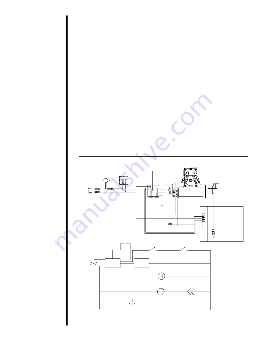
Figure 18. Direct Spark Ignition (DSI) Wiring Diagram

HI TEMP

LIMIT SWITCH

OPTIONAL REMOTE,

 WALL SWITCH

OR THERMOSTAT

(ON CERTIFIED UNITS ONLY)

BLACK

GROUND

FAN

REN

OPTIONAL

FAN

SWITCHES

L2

(NEUTRAL)

L2

(HOT)

JUNCTION

BOX

120 VAC

ON/OFF

1

2

0

 V

A

C

P

O

W

E

R

 C

O

R

D

GROUND TO

FIREPLACE

CHASSIS

WHITE

BLACK

FLAME SENSOR/SPARKER

IGNITION

MODULE

GAS

VALVE

HI-TEMP

LIMIT SWITCH

ON/OFF SWITCH

WHITE

YELLOW

GREEN

BLUE

WHITE

BLUE

DSI

MODULE

O

R

A

N

G

E

IGNITOR

DSI CONTROL VALVE

REMOTE OUTLET

FAN OUTLET

CONNECTORS

HOT

GROUND

NEUTRAL

Summary of Contents for Gas Fireplace

Page 1: ...ng or operating this appliance This manual must be left with appliance for future reference Heat N Glo a division of Hearth Technologies Inc 20802 Kensington Boulevard Lakeville Minnesota 55044 www heatnglo com 446 981EFC 8 01 Owner s Guide ...

Page 2: ...ROPER INSTALLATION ADJUSTMENT ALTERATION SERVICE OR MAINTENANCE CAN CAUSE INJURY OR PROPERTY DAMAGE REFER TO THIS MANUAL FOR ASSISTANCE OR ADDITIONAL INFORMATION CONSULT A QUALIFIED INSTALLER SERVICE AGEN CY OR THE GAS SUPPLIER This appliance is only for use with the type of gas indicated on the rating plate This appli ance is not convertible for use with other gases unless a certified kit is used...

Page 3: ... or near the appliance Children and adults should be ALERTED to the hazards of high surface temperature and should STAY AWAY to avoid burns or clothing ignition Young children should be CAREFULLY SUPERVISED when they are in the same room as the appliance These units MUST use one of the vent systems described in the Installing Your Fireplace section of the Installers Guide NO OTHER vent systems or ...

Page 4: ...The information contained in this Owners Guide unless noted otherwise applies to all models and gas control systems Your new Heat N Glo gas fireplace will give you years of durable use and trouble free enjoyment Welcome to the Heat N Glo family of fireplace products Consumer Reference Information We recommend that you record the following pertinent information about your fireplace Your Fireplace s...

Page 5: ...g surrounding household objects and building materials 8 Step 6 Purging air from the gas supply lines 8 Step 7 Preparing to light your fireplace 9 Step 8 Lighting your fireplace 10 Section 3 Maintaining and Servicing Your Fireplace 15 Fireplace Maintenance 15 Glass Assembly Care and Installation 17 Section 4 Troubleshooting 21 Standing Pilot Troubleshooting 21 DSI Troubleshooting 24 IPI Troublesho...

Page 6: ...nstallers Guide and Rating Plate for your fireplace Installation Codes The installation must conform with local codes or in the absence of local codes with the National Fuel Gas Code ANSI Z223 1 in the United States or CAN CGA B149 Installation Codes in Canada The appliance when installed must be electrically grounded in accordance with local codes or in the absence of local codes with the Nationa...

Page 7: ...side is called the controls compartment Figure 1 The Controls Compartment Step 2 Identifying the type of ignition system Here s how to identify a Standing Pilot Ignition system If your fireplace s gas controls have a red push button piezo ignitor you have a Standing Pilot Ignition system Figure 2 Standing Pilot Ignition Here s how to identify a Direct Spark Ignition DSI system If your fireplace s ...

Page 8: ... A GAS LEAK EXISTS FOLLOW THE RULES SHOWN BELOW 1 Evacuate all people from your building 2 DO NOT light matches DO NOT turn electric lights or switches on or off in the area DO NOT use an electric fan to remove gas from the area DO NOT use a telephone inside the building 3 Shut off the gas at the LP tank outside of your building 4 Telephone the gas company and the fire department Ask for instructi...

Page 9: ...on or the front grilles of your fireplace Before lighting the fireplace double check that furniture and other combustible household objects are NOT located within 36 inches of the fireplace front Step 4 Checking for obstructions blocking vent termination or front grilles H1 V H DIRECT VENT TERMINATION FRONT GRILLES B TYPE VENT TERMINATION Step 5 Checking surrounding house hold objects and building...

Page 10: ...all a qualified service tech nician Force or attempted repair may re sult in a fire or explosion D Do not use this appliance if any part has been under water Immediately call a qual ified service technician to inspect the ap pliance and to replace any part of the con trol system and any gas control which has been under water use any phone in your building Immediately call your gas supplier from a ...

Page 11: ...to HI to increase the flame height and counterclockwise to LO to decrease the flame height To turn the burner flame on or off Use the fireplace ON OFF rocker switch wall switch or remote control kit For Optimum Efficiency Turn the control valve to OFF when the appliance is not in operation Figure 6 Gas Valve Control and Pressure Regulator Knob CAUTION DURING THE INITIAL PURGING AND SUBSE QUENT LIG...

Page 12: ...AS CONTROL VALVE MODELS NOTE Knob cannot be turned from PILOT to OFF unless knob is pushed in slightly Do not force 4 WAIT AT LEAST FIVE 5 MINUTES TO CLEAR OUT ANY GAS If you have unsuccessfully tried to light the fireplace wait longer especially if you are using LP gas Then smell for gas including near the floor If you then smell gas STOP Follow B in the safety information on page 6 If you don t ...

Page 13: ... the ON OFF rocker switch to the OFF position and the burner will extinguish During the off season When the heating season is over turn the ON OFF switch to the OFF position The system will be shut down To turn the burner flame on or off Use the fireplace ON OFF rocker switch wall switch or remote control kit Figure 7 The DSI Control Valve and On Off Rocker Switch Lighting Your Direct Spark Igniti...

Page 14: ... Flash Normal operation call for heat 3 Two Flashes 5 minute trial lockout on off reset required 4 Steady On Hard lockout control failure Do not attempt to service or repair the equipment yourself Turn the ON OFF switch to OFF and call a qualified service technician 1 STOP Read the safety informa tion on page 9 first 2 Turn off all electric power to the appliance 3 This appliance is equipped with ...

Page 15: ...G INSTRUCTIONS IPI GAS VALVE TO TURN OFF GAS TO APPLIANCE 1 Turn off all electric power to the appliance if service is to be performed 2 Flip ON OFF switch to the OFF position 5 Turn on all electric power to the appli ance 6 To light the burner flip the ON OFF switch to the ON position The ON OFF switch may include a wall switch if so equipped 7 If the appliance will not operate fol low the instru...

Page 16: ...ce s Flame Service flame patterns Make sure the flames Patterns Technician are steady not lifting or floating See Flame Height Owner the picture in Figure 9 The flame sensor or thermopile thermocouple tips should be covered with flame See the picture in Figure 10 Checking Before initial use Qualified Inspect the external vent cap on a Vent System and at least Service regular basis to ensure that n...

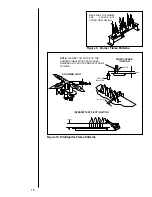
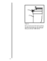
Page 17: ...DY NOT LIFTING OR FLOATING NOTE FLAMES TOO CLOSE TO THE CERAMIC INSULATORS CAN CAUSE NUISANCE LOCKOUTS AND ELECTRODE FAILURE Figure 10 Pilot Ignitor Flame Patterns Figure 9 Burner Flame Patterns 1 4 6mm IGNITOR 3 8 10mm CERAMIC INSULATOR 11 16 INTERMITTENT PILOT IGNITION ...

Page 18: ...llow the glass to cool completely Remove the glass using the appropriate removal instructions Clean the glass with any common household glass cleaner and soft cloth Cleaning the glass after the initial 3 to 4 hour burn will prevent the film from becoming baked on to the glass After this initial cleaning it should only be necessary to clean the glass occasionally as required NEVER SCRAPE OR RUB GLA...

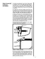
Page 19: ...p of glass towards you WARNING PULLING GLASS TOO FAR AWAY FROM FIREPLACE WITHOUT FIRST LIFTING IT OUT OF THE BOTTOM BRACKET WILL DAMAGE THE BOTTOM BRACKET After replacement latch the tension spring bolt into the latch bracket and turn the spring bolt turn ENSURE THAT THE SPRING BOLTS ARE SECURELY LATCHED Reinstall any trim door or louvers Remove wing nuts and glass clips After replacement re insta...

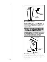
Page 20: ...s seated firmly in the glass frame slot Reinstall any trim door or louvers Figure 15 Glass Removal Remove any door fronts Use a phillips screwdriver to loosen and remove the top bracket before loosening the remaining screws and tilting the glass away from the unit After replacement set bottom of glass in the bottom bracket and press the top of glass against the unit Replace the bracket and screws ...

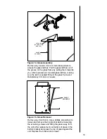
Page 21: ...move or lower any trim doors Remove the wing nuts glass clips and glass door After replacement replace the wing nuts and glass clip Hand tighten the wing nuts DO NOT OVERTIGHTEN Figure 16 WING NUT GLASS DOOR ...

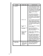
Page 22: ... and wires for proper connections Place the jumper wires across the terminals at the switch If the burner comes on replace the defective switch If the switch is OK place the jumper wires across the switch wires at the gas valve If the burner comes on the wires are faulty or connections are bad If the pilot flame is not close enough physically to the thermopile adjust the pilot flame Be sure the wi...

Page 23: ...eading is below the minimum Turn the valve knob to the ON position Place the ON OFF switch in the ON position Check the millivolt meter at the thermopile terminals The millivolt meter should read greater than 125mV If the reading is acceptable and if the burner does not come on replace the gas valve Check the burner orifice for stoppage Remove stoppage Follow the corrective action in Symptom and P...

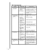
Page 24: ...e of debris Ensure that the vent system joints are tight and have no leaks Ensure that no debris has been placed in the area at the base of or in the area of the air holes in the center of the base pan beneath the burner Ensure that the glass is tightened properly on the unit particularly on top corners Possible Cause a No LP in the tank b Inner vent pipe leaking exhaust gases back into the system...

Page 25: ...t cap is installed properly and free of debris Ensure that the inner vent pipe has no leaks in it Ensure that the glass is tightened properly on the unit particularly on the top corners Symptom 1 The main burner does not light 2 The main burner extinguishes while in operation 3 The glass soots 4 The flame burns blue and lifts off the burner Possible Cause a Unit junction box not electrically groun...

Page 26: ...with the pilot lit Connect a wire from red battery connection red wire to green terminal of valve If valve opens and burner lights replace the module If it does not replace the valve Check connection of green wire to green terminal on valve Disconnect orange wire on valve If the pilot remains lit replace faulty valve Disconnect orange wire on valve If the pilot turns off then check all connections...

Page 27: ...ent pipe has no leaks in it Ensure that the glass is tightened properly on the unit particularly on the top corners Symptom 4 The main burner extinguishes while in operation 5 The glass soots 6 The flame burns blue and lifts off the burner Possible Cause a No fuel supply b Loose wire connection on module or valve c High temperature limit switch where applicable d Flame does not engulf flame sensor...

Page 28: ...DS TO PREVENT ACCIDENTAL FIREPLACE OPERATION Wall Switch Position the wall switch in the desired position on a wall Run a maximum of 25 feet 7 8 m or less length of 18 A W G minimum wire and connect it to the fireplace ON OFF switch pigtails DO NOT CONNECT 110 120 VAC TO THE WALL SWITCH OR THE CONTROL VALVE WILL BE DESTROYED CAUTION LABEL ALL WIRES PRIOR TO DISCONNECTION WHEN SERVICING CONTROLS WI...

Page 29: ...n a maximum of 25 feet 7 8 m or less of 16 A W G minimum Romex wire and connect it to the fireplace ON OFF switch pigtails CAUTION LABEL ALL WIRES PRIOR TO DISCONNECTION WHEN SERVICING CONTROLS WIRING ERRORS CAN CAUSE IMPROPER AND DANGEROUS OP ERATION VERIFY PROPER OPERATION AFTER SERVICING Figure 18 Direct Spark Ignition DSI Wiring Diagram HI TEMP LIMIT SWITCH OPTIONAL REMOTE WALL SWITCH OR THERM...

Page 30: ...NG CONTROLS WIRING ERRORS CAN CAUSE IMPROPER AND DANGEROUS OP ERATION VERIFY PROPER OPERATION AFTER SERVICING Figure 19 Intermittent Pilot Ignition IPI Wiring Diagram If Your Fireplace Has Intermittent Pilot Ignition IPI NOTE 1 Ignition module valve pilot and wall switch operate on 3 volts 120 VAC is required at junction box unless equipped with battery back up NEUTRAL GROUND REMOTE CONTROL HOT LO...

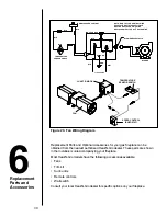
Page 31: ...ng accessories available Fans Trim kit Surrounds Remote controls Wall switch Consult your local Heat N Glo dealer for specific options on your fireplace 6 FAN TEMPERATURE SENSOR SWITCH SPEED CONTROL RHEOSTAT JUNCTION BOX NOTE IF ANY OF THE ORIGINAL WIRE AS SUPPLIED WITH THE APPLIANCE MUST BE REPLACED IT MUST BE REPLACED WITH TYPE 105 C RATED WIRE O JUNCTION BOX VARIABLE SPEED CONTROL TEMPERATURE S...

Reviews: