24
Heat-Timer Corp.
Minimum Run Time
(Available with PID Control Logic Only)
Adjustable from 1 minute to 60 minutes
Default: 2 minutes
SELECT
Settings/System Settings/More Settings/Stage Settings/Min Runtime
• It is the minimum amount of time any stage will run. It reduces short cycling.
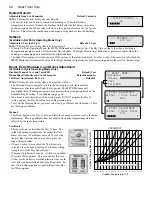
-- MINIMUM RUNTIME--
2m
[
]
• For the lowest stage on a burner, the Minimum Run Time starts after the purge delay.
• In addition to the Minimum Run Time, the Last Stage Hold applies to the last stage online.
• Initially, set the Minimum Run Time to half the Reaction Time.
• If System tends to overshoot, reduce the Minimum Run Time. If boilers tends to short cycle, increase Minimum Run Time.
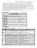
-- STANDBY DELAY --
10m
[
]
Standby Delay
(Available with PID Control Logic Only)
Adjustable from 1 minute to 60 minutes
Default: 10 minutes
SELECT
Settings/System Settings/More Settings/Stage Settings/Standby Delay
• The Standby Delay time only applies to boilers in Standby Mode.
• A Standby Boiler can only be activated after all the boilers in Auto Mode have run at high fire for the full Standby Delay.
• Standby boilers are usually used for backup or extreme load conditions. A Standby boiler can never be a Lead Boiler
• The full Standby Delay must always elapse regardless of what happens the system pressure. Therefore, a shorter Standby Delay
will result in smoother set point operation in extreme conditions. Longer Standby Delay may prevent a standby boiler from firing
if the other boilers can eventually meet the load or if the load decreases.
• When setting Standby Delay, remember that it will be added to the Reaction Time for the first stage on the first Standby boiler. The
following stages start time will rely on the Purge Delay and Reaction Time only.
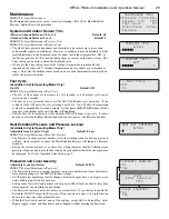
- LAST STAGE HOLD -
0.0 psi
[ ]
Last Stage Hold
(Available with PID Control Logic Only)
Adjustable from 0°F to 30°F
Default: 5°F
SELECT
Settings/System Settings/More Settings/Stage Settings/Lst Stage Hold
• The Last Stage Hold prevents short cycling of the Lead Stage during low load conditions.
• In low load conditions, the system might have a load that is significantly less than the output of one Stage. When the MPCQ
Platinum brings on the Lead Stage, the Set Point is quickly exceeded and the MPCQ Platinum turns the Lead Stage off.
• To prolong the run time during this type of condition, use the Last Stage Hold setting. The MPCQ Platinum will allow the system
pressure to exceed the Set Point by the Last Stage Hold value before the Lead Stage is turned off.
• For example; with a Set Point of 10 Psi and a Last Stage Hold setting of 2 Psi, the Lead Stage boiler will remain on until the Set
Point reaches 12 Psi then de-energize.
Avoiding Conflicting Boiler Limits
The pressure limits set on the boilers MUST be set considerably higher than the MPCQ
Platinum’s Set Point for the reasons detailed below.
• The System sensor is located on the common header some distance from the boilers.
• As the pressure rises in the header and before reaching the sensor location, energy
is dissipated and due to steam characteristics and steam pipe length, pressure drops.
Therefore, the pressure in the header will be lower than that registered by the boilers.
ALERT
The pressure limits set on the
boilers must be higher than the
MPCQ Platinum Set Point. Read
the section at left for details to
prevent erratic system operation.
• In addition to the normal drop experienced between the boiler pressure and that read by the MPCQ Platinum sensor, the Last Stage
Hold setting must be accounted for. The boiler limit must be set above the Set Point PLUS the Last Stage Hold PLUS the normal
drop experienced in the piping.
• Using the previous example of a 2 Psi Last Stage Hold with a 10 Psi Set Point, the boilers’ limits must be set enough over 12 Psi to
prevent the boilers’ internal limits from being reached. In this situation, the boiler high limit should be set at approximately 14 Psi.
Throttle
(Available with OSS Control Logic Only)
Adjustable from 0.5 Psi to 5.0 Psi
Default: 1.0 Psi
SELECT
Settings/System Settings/More Settings/Stage Settings/Throttle
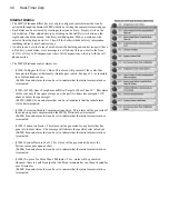
----- THROTTLE -----
1.0 psi
[
]
• The Throttling sets a pressure band around the Set Point that controls when stages will be turned on or off.
• For example, in the Oversize (OSS) Control Logic, no stages will be activated until the pressure falls one full Throttle below the
Set Point. A second stage will be activated when the pressure falls to two full Throttles below the Set Point, and so on, with one
extra stage being turned on for every Throttle below the Set Point the System pressure reaches.
• Stages will be turned off as the pressure rises toward the Set Point with one full Throttle as a difference.
• The last stage to be turned off will be allowed to exceed the Set Point by a full Throttle before it is turned off. This helps prevent
the last stage from short cycling when the load is low or when the stage is oversized.


