background image

16

PREPARATION

RETURN

SOLAR PANEL

CIRCULATOR

GAUGE

FOR SOLAR SENSOR

DRY WELL

LINE

EXHAUST VENT

INTAKE AIR

AIR VENT

BALL

VALVE

BACKFLOW

LINE

VALVE MANUFACTURER.

DRAIN VALVE

TEMP/PRESSURE

EXPANSION

PREVENTER

SOLAR 

(see note 4)

DRAIN

COLD WATER

MIXING VALVE SHOWN.

CLOSED LOOP

RELIEF VALVE

VENT

OUTLET

MANUAL

FOR OTHER VALVES, CONSULT

PANEL

 TANK

COLD IN

AUXILIARY

HOT WATER

VALVE

HOT OUT

CONNECTION

AUXILIARY
CONNECTION

TANK

RE-CIRCULATED

CONDENSATE

SUPPLY

GAS

EXPANSION

INLET

TEMP/PRESSURE

SOLAR PANEL

SPARCO AQUAMIX

EXPANSION

CONDENSATE

AUXILIARY

TEMP/PRESSURE

FOR OTHER VALVES, CONSULT

CONNECTION

LINE

VALVE MANUFACTURER.

MANUFACTURER FOR PROPER SIZING

BALL

INTAKE AIR

 TANK

COLD IN

SOLAR 
PANEL

RELIEF VALVE

AIR 

RE-CIRCULATED

GAS

(see note 4)

CIRCULATOR

HOT WATER

HOT OUT

COLD WATER

INLET

AIR VENT

AUXILIARY

CONNECTION

SOLAR PANEL
RETURN

SOLAR PANEL
SUPPLY

GAUGE

TEMP/PRESSURE

HANDLER *

VALVE

VENT

EXHAUST VENT

MANUAL

OUTLET

CLOSED LOOP

PREVENTER

VALVE

BACKFLOW

DRAIN VALVE

DRY WELL

FOR SOLAR SENSOR

TANK

EXPANSION

( see note 4)

CIRCULATOR

DRAIN

LINE

SPARCO AQUAMIX

MIXING VALVE SHOWN.

*

C

HECK WITH AIR HANDLER

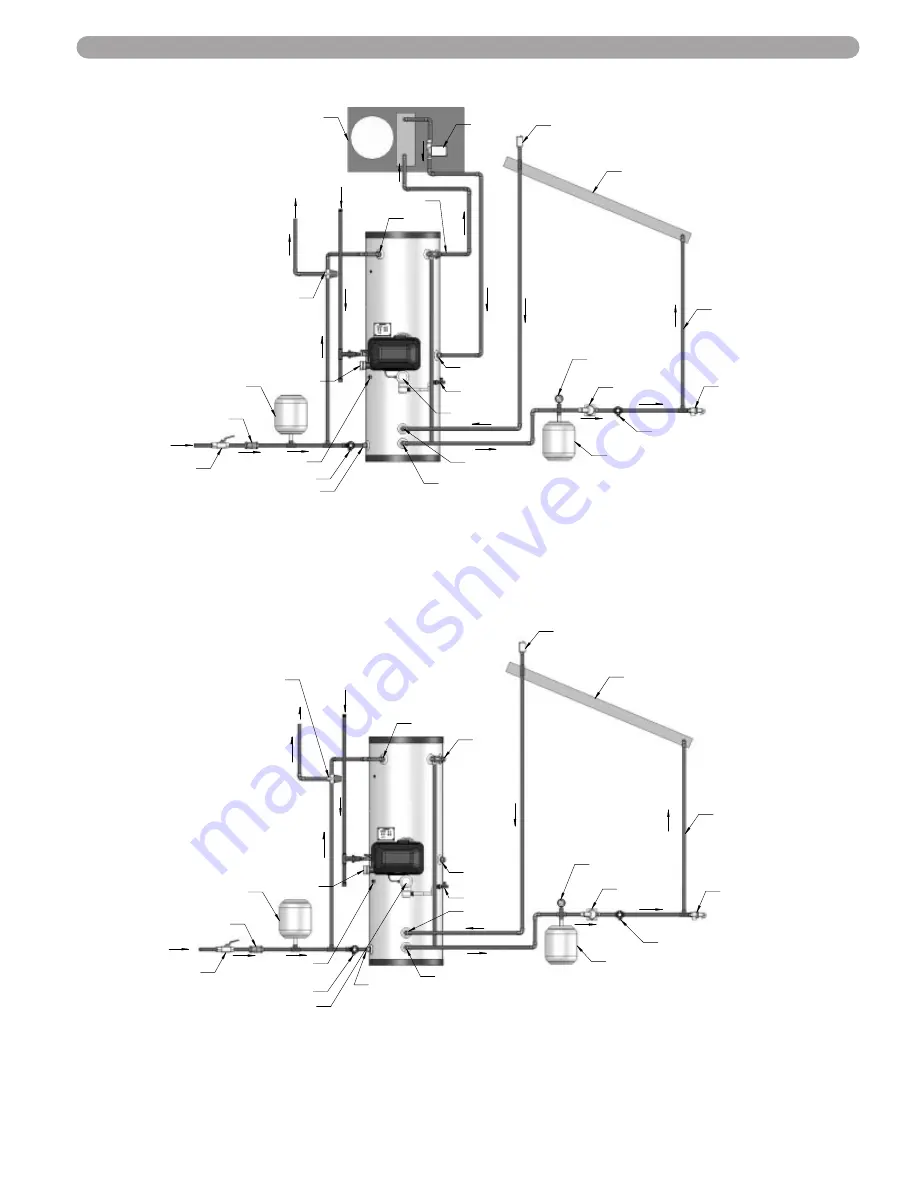
PHOENIX SOLAR PIPING WITH AIR HANDLER

PHOENIX SOLAR PIPING

NOTES:
1. Minimum pipe size should match connection size on Phoenix. If you require greater flow, upsize the pipe accordingly.
2. A Thermal Expansion tank suitable for potable water must be sized and installed within this piping system between the check

valve and the cold water inlet of the Phoenix.

3. Gas Line must be rated to the maximum input capacity of the unit. Unit must have 10 feet of pipe after gas regulator.
4. All circulators shall have an integral flow check.

LP-201-A

7/16/07

LP-179-R

7/16/07

Summary of Contents for Gas Fired

Page 1: ... Installation Operation Maintenance 2007 Heat Transfer Products Inc ...

Page 2: ...e vicinity of this or any other appliance WHAT TO DO IF YOU SMELL GAS Do not try to light any appliance Do not touch any electrical switch do not use any phone in your building Immediately call your gas supplier from a neighbor s phone Follow the gas supplier s instructions If you cannot reach your gas supplier call the fire department Installation and service must be performed by a qualified inst...

Page 3: ... Gas Piping D Gas Table E Dungs Gas Valve Part 5 Venting Combustion Air And Condensate Removal 19 27 A Installing Exhaust Vent and Intake Air Vent B General C Approved Materials for Exhaust Vent and Intake Air Vent D Exhaust Vent and Intake Air Vent Pipe Location E Exhaust Vent and Intake Air Vent Sizing F Longer Vent Runs G Exhaust Vent and Intake Air Pipe Installation H Water Heater Removal from...

Page 4: ... touch any electric switch do not use any phone in your building Immediately call your gas supplier from a neighbor s phone Follow the gas suppliers instructions If you cannot reach your gas supplier call the fire department SPECIAL ATTENTION BOXES The following defined terms are used throughout this manual to bring attention to the presence of hazards of various risk levels or to important inform...

Page 5: ...let water temperature set point 6 Control The integrated control system monitors the upper and lower water temperature and regulates the fan speed to regulate the unit s BTU output This allows the unit to only deliver the amount of heated energy required and nothing more 7 Burner Constructed of high grade stainless steel construction the burner uses pre mixed air and gas and provides a wide range ...

Page 6: ...igh temperature Regular scheduled maintenance must be established to monitor and maintain the proper PH level of the heat transfer fluid in the system to protect the heat exchanger and other components of the system PART 3 PREPARE WATER HEATER LOCATION A INSTALLATIONS MUST COMPLY WITH Local state provincial and national codes laws regulations and ordinances National Fuel Gas Code ANSI Z223 1 lates...

Page 7: ...oving it from the space See Fig 3 1 at right 03 22 07 LP 179 T CLEARANCE ZERO 12 MIN 12 MIN CLEARANCE CLEARANCE CLEARANCE 24 MIN SERVICE CLEARANCE Fig 3 1 Phoenix Top View PART 3 PREPARE WATER HEATER LOCATION CONTINUED n WARNING Failure to keep water heater area clear and free of combustible materials gasoline and other flammable liquids and vapors can result in severe personal injury death or sub...

Page 8: ...engths routing and termination method must all comply with the methods and limits given in the Venting section F PREVENT COMBUSTION AIR CONTAMINATION Install intake air piping for the Phoenix Water Heater as described in the Venting section Do not ter minate exhaust in locations that can allow contamination of intake air PART 3 PREPARE WATER HEATER LOCATION CONTINUED n WARNING You must pipe outsid...

Page 9: ...or smoke from a cigarette cigar or pipe f After it has been determined that each appliance remaining connected to the common venting system properly vents when tested as outlined herein return doors windows exhaust fans fireplace dampers and any other gas burning appliance to their previous conditions of use g Any improper operation of common venting system should be corrected so the installation ...

Page 10: ...ions Corrosion damage and heater failures resulting from water pH levels of lower than 6 or higher than 8 are non warrantable The ideal pH range for water used in a storage tank or a water heater system is 7 2 to 7 8 3 Total Dissolved Solids Total dissolved solids TDS is a measure of all minerals and solids that are dissolved in the water The concentration of total dissolved solids is usually expr...

Page 11: ...s require back flow preventers on all incoming water supplies The hot water expansion tank must be listed for potable water use The expansion tank should be located on the cold inlet piping close to the water heater n CAUTION The expansion tank must be suitable for hot potable water PART 3 PREPARE WATER HEATER LOCATION CONTINUED n WARNING Following installation of the T P Relief Valve the valve le...

Page 12: ...stem A thermal trap or heat trap loop may be installed here to provide additional energy savings and prevent the thermal siphoning of domestic hot water L AUXILIARY CONNECTIONS The auxiliary connections are additional connections for an air handlers plate exchangers or other devices that supply hot water These connections must be installed in accordance with all local and national codes or any app...

Page 13: ...equire greater flow upsize the pipe accordingly 2 A Thermal Expansion tank suitable for potable water must be sized and installed within this piping system between the backflow preventer and the cold water inlet of the Phoenix 3 Gas line must be rated to the maximum input capacity of the unit Unit must have 10 feet of pipe after gas regulator 4 All circulators shall have an integral flow check AIR...

Page 14: ...rs shall have an integral flow check 3 Gas line must be rated to the maximum input capacity of the unit Unit must have 10 feet of pipe after gas regulator 1 Minimum pipe size should match connection size on Phoenix If you require greater flow upsize the pipe accordingly 2 A Thermal Expansion tank suitable for potable water must be sized and installed within this piping system between the check val...

Page 15: ...ty of the unit Unit must have 10 feet of pipe after gas regulator 4 All circulators shall have an integral flow check NOTE This drawing is meant to show system piping only The installer is responsible for all equipment and detailing required by local codes VALVE BACKFLOW PREVENTER VALVE PURGE PLATE BRAZED CLOSED LOOP RADIANT HEATING AIR ELIMINATOR BALL VALVE AUXILIARY GAUGE PRESSURE RADIANT HEAT V...

Page 16: ...f the unit Unit must have 10 feet of pipe after gas regulator 4 All circulators shall have an integral flow check SPECIAL NOTE Drains and Check valve connected between the Phoenix and the Storage Tank will assist in purging air from system BALL VALVE COLD WATER SHUT OFF OUTLET CONNECTION INLET BACKFLOW HOT WATER PREVENTER AUXILIARY TANK EXPANSION CONNECTION HOT OUT PHOENIX WITH STORAGE TANK AUXILI...

Page 17: ...VALVE DRY WELL FOR SOLAR SENSOR TANK EXPANSION see note 4 CIRCULATOR DRAIN LINE SPARCO AQUAMIX MIXING VALVE SHOWN CHECK WITH AIR HANDLER PHOENIX SOLAR PIPING WITH AIR HANDLER PHOENIX SOLAR PIPING NOTES 1 Minimum pipe size should match connection size on Phoenix If you require greater flow upsize the pipe accordingly 2 A Thermal Expansion tank suitable for potable water must be sized and installed ...

Page 18: ...icated drip leg as shown in the illustra tion at right per the National Fuel Gas Code You must ensure that the entire gas line to the con nection at the Phoenix Water Heater is no smaller than Once all the inspections have been performed the piping must be leak tested If the leak test requirement is a higher test pressure than the maximum gas inlet pressure you must isolate the Phoenix from the ga...

Page 19: ...ile in operating dynamic mode at full output If an in line regulator is used it must be a minimum of 10 feet from the Phoenix It is very important that the gas line is properly purged by the gas supplier or utility Failure to properly purge the lines or improper line sizing will result in ignition failure This problem is especially noticeable in NEW LP installations and also in empty tank situatio...

Page 20: ...he gas supply or the to decrease the gas supply This adjustment will affect CO CO levels Make sure the levels GAS SHUT OFF VALVE COMBUSTION AIR n DANGER The Phoenix must be vented as detailed in Venting section Ensure the exhaust and intake piping comply with these instructions regarding vent system Inspect finished combustion air intake and exhaust piping thoroughly to ensure all joints are well ...

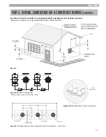
Page 21: ... water heater is approved for zero clearance to combustible construction b See illustration within this section of clearances for location of exit terminals of direct vent venting systems c This water heater vent system shall terminate at least 3 feet 0 9 m above any forced air intake located within 10 ft 3 m Note this does not apply to the combustion air intake of a direct vent appliance d Provid...

Page 22: ...ust directly under roof overhangs to prevent icicles from forming i Provide 4 feet clearance from the inside corner of vertical walls chimneys etc as well as horizontal corners created by roof overhangs 2 Determine air intake vent location a Provide 1 foot clearance from the bottom of the intake air vent and the level of maximum snow accumulation Snow removal may be necessary to maintain clearance...

Page 23: ...echanical draft and direct vent venting systems Reference National Fuel Gas Code ANSI Z223 1 NFPA 54 2002 Fig 5 2 Multiple Vent Spacing Note Exhaust must extend out 1 foot Figure 5 4 Multiple Water Heater Installations Fig 5 3 Multiple Stainless Steel Horizontal Vent Kit Installation Front View Fig 5 1 ...

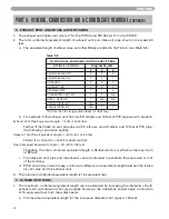
Page 24: ...ivalent length is 46 feet which is well below the maximum of 85 feet c The intake air vent pipe and the exhaust vent are intended to penetrate the same wall or roof of the building d Effort should be made to keep a minimum difference in equivalent length between the intake air vent pipe and the exhaust vent 3 The minimum combined equivalent length is 16 equivalent feet F LONGER VENT RUNS 1 The max...

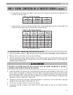
Page 25: ...ipe must be piped around an obstacle that results in the creation of a low point condensate will collect in this low point and form a blockage This condensate must be drained away using a field installed condensate drain assembly as shown See Fig 1 Section 5 5 All piping must be fully supported Use pipe hangers at a minimum of 4 foot intervals to prevent sagging of the pipe where condensate may fo...

Page 26: ...andle or smoke from a cigarette 6 After it has been determined that each appliance remaining connected to common venting system properly vents when tested as outlined return doors windows exhaust fans fireplace dampers and any other gas burning appliance to their previous condition of use 7 Any improper operation of the common venting system should be corrected so the installation conforms with th...

Page 27: ... THE DRAIN LINE 2 PLASTIC PIPE SHOULD BE THE ONLY MATERIAL USED FOR THE CONDENSATE LINE STEEL BRASS COPPER OR OTHERS WILL BE SUBJECT TO CORROSION OR DETERIORATION 3 IT IS ALSO VERY IMPORTANT THAT THE CONDENSATE LINE IS NOT EXPOSED TO FREEZING TEMPERATURES OR ANY OTHER TYPE NOTES CAUTION The condensate line must remain unobstructed allowing free flow of condensate If condensate is allowed to freeze...

Page 28: ...IN WHICHEVER IS GREATER 12 OVER MAXIMUM SNOW LEVEL OR 24 AND COUPLING EXHAUST INTAKE ROOF VENT WITH TEE INTAKE EXHAUST SUPPORT BRACKETS MUST BE USED ON ALL HORIZONTAL AND VERTICAL PIPING LEFT SIDE VIEW 24 MIN 10 0 MIN GREATER 12 OVER MAXIMUM SNOW LEVEL OR 24 WHICHEVER IS NOTE EXTENDED VENT RUNS WHEN TRANSITIONING TO A LARGER DIAMETER MUST ALWAYS TAKE PLACE IN A VERTICAL POSITION TO PREVENT CONDENS...

Page 29: ...replacement condensate trap control replacement etc A OPERATING INSTRUCTIONS If you smell gas STOP Follow listed safety instructions above If you do not smell gas follow the next steps 1 Turn on all electric power to appliance Make sure tank is full with cold water and purge all piping To assure adequate purging open all hot water faucets 2 Adjust the temperature setpoint of the Phoenix if desired...

Page 30: ...tus bus communication co connected nc not connected d11 32 Not used d12 Power On Hours Example Hours x 1000 Ex 0 1 100 hrs or 1 0 1000 hrs d13 Total Water Heating Hours TW Hrs x 1000 d14 0 Not used d15 Passed Ignition Attempts Passed ignition x 1000 D TEST MODE This function is intended to simplify the gas valve adjustment if needed Listed below are the recom mended limits on each Phoenix Water He...

Page 31: ...place and drywall or saw dust away from appliance COMBUSTION SETTINGS HIGH FIRING RATES and LOW FIRING RATES ON ALL MODELS Natural Gas Propane LP low high low high Carbon Monoxide CO 0 20 ppm 20 ppm 30 ppm 0 20 ppm 40 ppm 60 ppm Carbon Dioxide CO2 8 9 8 9 9 10 9 10 Fig 6 1 Fig 6 2 PART 6 START UP PROCEDURE CONTINUED n CAUTION In unusually dirty or dusty conditions care must be taken to keep applia...

Page 32: ...31 WIRING F INTERNAL WIRING PART 6 START UP PROCEDURE CONTINUED Phoenix Connector Diagram ...

Page 33: ... problem exists with either the appliance the controls or the gas supply Under such circumstances a qualified service technician should be contacted immediately to properly service the appliance and correct the problem If a technician is not available depress ing the S4 RESET button once will remove the lockout state so additional trials for ignition can be performed The unit will try to re light ...

Page 34: ...cted n WARNING Do not use this appliance if any part has been under water Improper or dangerous operation may result Contact a qualified service technician immediately to inspect the heater and repair or replace any part of the water heater which has been under water n DANGER When servicing or replacing components that are in direct contact with the heater water be certain that There is no pressur...

Page 35: ...bustion air fan speed less than 70 of expected 60 Sec 1 Check the combustion air fan wiring 2 Replace the combustion air fan 3 Replace the control board E14 Combustion Fan Speed High The com bustion air fan speed is more than 130 of expected 60 Sec 1 Check the combustion air fan wiring 2 Replace the combustion air fan 3 Replace the control board PR0 Low Water Cut Off Until Corrected 1 Assure that ...

Page 36: ...oenix will relight 3 times before the control goes into this lockout condition 1 Monitor the gas pressure to the unit while in operation 2 Assure that the flame is stable when lit 3 Check to see if the green light on the display module is out while the water heater is running 4 If the green light doesn t come on or goes off during operation check the flame signal on the status menu 5 If the signal...

Page 37: ... 4 11 3 4 6 PH 80 45 36 GALLONS 64 PH 119 F 13 17 13 1 2 119 7 1 2 66 7 1 2 14 1 4 66 27 SHIPPING 52 5 13 1 4 9 3 4 PHOENIX WATER HEATER DIMENSIONS MODEL PHOENIX WATER HEATER SPECIFICATIONS MODEL GALLONS BTU S AIR INTAKE EXHAUST VENT SIZE WATER INLET OUTLET SIZE AUXILIARY CONN GAS LINE CONN SYSTEM RELIEF PIPE SIZE SHIPPING WEIGHT PH 55 55 100 000 130 000 199 000 2 3 1 NPT 1 3 4 3 4 175 LBS PH 80 8...

Page 38: ...WATER INLET OUTLET SIZE HEAT EXCHANGER SIZE AUXILIARY CONN GAS LINE CONN SYSTEM RELIEF PIPE SIZE SHIPPING WEIGHT PH 80S 80 130 000 199 000 2 3 1 1 2 NPT 1 1 3 4 3 4 235 LBS PH 119S 119 130 000 199 000 2 3 1 1 2 NPT 1 1 3 4 3 4 405 LBS OUTLET HOT WATER SAFETY HIGH LIMIT CUT OFF LOW WATER SENSOR UPPER TEMP SENSOR LOWER TEMP INLET COLD WATER CONTROL WELL C A B D EXHAUST CONDENSATE LINE HEAT EXHANGER ...

Page 39: ...250P 302 8 Thermodisc Flue ECO 210 7250P 089 9 Hose Barb 1 4 x 10 32 Blocked Vent Pressure Switch 7250P 154 10 Plastic Tubing 3 16 ID Blocked Vent Pressure Switch 7000P 805 11 Stainless Steel Control Well PMW 3SENP 1 12 2 Trap Adapter 9500 0025 13 2 3 Air Inlet Adapter 199 000 BTU ONLY F3000 14 Lower Temperature Sensor 7100P 005 15 Snap Bushing 2500 0057 16 Upper Temperature Sensor 7100P 004 17 Lo...

Page 40: ...amp Condensate Hose 7250P 302 8 Thermodisc Flue ECO 210 7250P 089 9 Hose Barb 1 4 x 10 32 Blocked Vent Pressure Switch 7250P 154 10 Plastic Tubing 3 16 ID Blocked Vent Pressure Switch 7000P 805 11 2 Trap Adapter 9500 0025 12 2 3 Air Inlet Adapter 199 000 BTU ONLY F3000 13 Lower Temperature Sensor 7100P 005 14 Snap Bushing 2500 0057 15 Upper Temperature Sensor 7100P 004 16 Low Water Cut off Sensor ...

Page 41: ...50 23 Mounting Plate 7100P 027 8 Housing Swirl Plate 7100P 017 24 Gasket Spark Electrode 7100P 028 9 Gas Valve DUNGS 7100P 039 100 130 BTU 25 Spark Electrode 7100P 029 7100P 040 199 BTU 26 Gasket Burner 7100P 030 10 Screws M5 x 12 Slotted Countersunk Gas Valve 7100P 046 27 Burner 7100P 032 100 130 BTU 11 Tube Air Inlet 7100P 018 7100P 031 199 BTU 12 Gas Valve Inlet Flange 7100P 019 28 Adapter Mani...

Page 42: ...e settings programmed Electrical Connections Check wire connections make sure they are tight Smoke and CO detector Verify devices are installed and working properly change batteries if necessary Circuit breakers Check to see that the circuit breaker is clearly labeled exercise circuit breaker Chamber and Burner Combustion Chamber Check burner tube and combustion chamber coils clean according to ma...

Page 43: ...e for leaks Check piping for leaks and verify they are all properly supported Combustion Check CO CO2 Levels Check levels of CO and CO2 in Exhaust See Fig 6 1 in Startup Procedure for ranges record at high and low fire Safeties ECO Energy Cut Out Check continuity on Flue and Water ECO replace if corroded Water Pressure Switch Check operation check for signs of leakage replace if corroded Thermisto...

Page 44: ... 2007 Heat Transfer Products Inc LP 179 REV 7 11 07 ...

Reviews: