STP SERIES Install, Operation, and Maintenance Manual
SECTION 3: OPERATION AND CONTROLS
Rev-1
Diversified Heat Transfer, Inc.
•
439 Main Road, Route 202
•
Towaco, New Jersey 07082
Page
39
of
97
STP Manual
PHONE: 800-221-1522
•
WEBSITE: www.dhtnet.com
09/11/2019
the control valve, stopping the flow of boiler water or HTHW supply to heat exchanger.
When unit goes back to normal operating temperature conditions, unit status changes to
green in color, but the siren continues until alarm silence pushbutton is pressed manually.
6.
The low temperature alarms are default set to 20
°
F below the set point. If domestic water
outlet temperature reading is equal to or lower than this number, the unit status changes
from green to red in color and “LOW TEMP ALARM” message starts flashing in red color
on the center top side of the HOME screen. This merely serves as a warning that unit is
not able to maintain the target setpoint.
7.
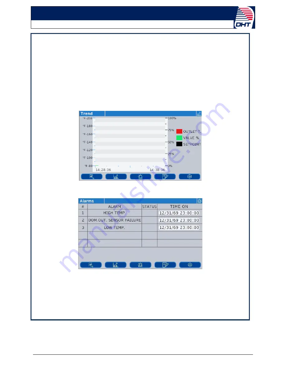
The “Trend screen” shown below displays the real-time trend graphs of domestic outlet &
inlet water temperatures, setpoint and control valve output open percentage as explained
in Section 3.9.1 This screen is empty on the startup. It starts logging data and displaying
graphs as soon as the unit is started.
8.
The “Alarms screen” shown below displays
the status of the standard alarms, whether
each alarm is active or not along with time and date when it occurred.
9.
The “Contact Information screen” shown below displays the DHT factory and local sales
representative company contact information as well as the serial number information of
controller and water heater, which are preconfigured before unit is shipped from factory.
Each unit is factory configured to display appropriate information on this screen.


