background image

14

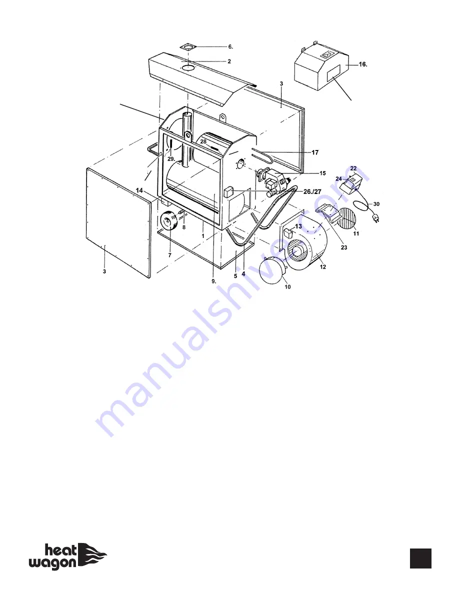
ITEM

PART#

DESCRIPTION

1

HWP 2109001

HEATER FRAME

2

HWP 2109002

COVER PLATE

3

HWP 2109003

SIDE PANELS (2)

4

HWP 2109004

REAR HANDLE

5

HWP 2109005

BOTTOM PLATE

6

HWP 2109006

FLUE COLLAR

7

HWP HW1065

WHEEL

8

HWP 2109008

WHEEL SHAFT

9

HWP 2109009

BURNER CHAMBER ASSEMBLY

10, 11

HWP 2109010

FAN GUARD

12

HWP 12440

FAN

13

HWP 40900

FAN CONNECTION BOX

14

HWP 2109014

FORKLIFT EYE

15

HWP 120008B

BURNER VG400

16

HWP 2109016

BURNER COVER

17

HWP 211153

OIL PREHEAT COIL 

22

HWP 41000

MAIN CONTROL BOX

23

HWP 2109023

BRACKET, MAIN CONTROL BOX

24

HWP 26400

MAIN SWITCH

25A

HWP 21800

OVERHEAT LIMIT SWITCH(bimetallic)

25B

HWP 21400**

OVERHEAT LIMIT (CAPILLARY)

26

HWP 40850

THERMOSTAT BOX

ITEM

PART#

DESCRIPTION

27

HWP 20579

HEATER CONTROL UNIT

28

HWP 20581

FAN SENSOR (4” SENSOR) 

29

HWP 20582

BURNER SENSOR 

30

HWP HC1020

POWER CORD & PLUG

31

HWP 36811

RUBBER GROMMET

32

HWP 210938

PLASTIC WINDOW W/BRACKET

33

HWP 2109037

12” BLACK OUTLET ADAPTER

34 

HWP 20583

FAN SENSOR (8” SENSOR)

NOT SHOWN IN DIAGRAM

HWP 2436

CONTACTOR

HWP 46950

CAPACITOR

HWP 80200

BURNER COVER LATCH

HWP 2109031

RADIATION SHIELD (UPPER)

HWP 12000

SMOKE FLUE W/RAIN CAP

HPW 2109033

RADIATION SHIELD (SIDE)

HWP 2453

REMOTE THERMOSTAT (w/o cord)

HWP 100428

GASKET FOR 120008 OR 120008B

HWP  21724011

FLANGE ADJ. FOR 120008 OR 12008B

HWP 62459002 ORIFICE PACK FOR 120008B 
HWP 40850SS

SILICONE SEAL - 40850 THERM. BOX

ACC 40SV06

OPTIONAL REGULATOR FOR MORE 
THAN 14” W.C.

HWP 210047

RUBBER EDGE SEAL (SOLD PER FOOT)
(30 FEET PER HEATER)

HWP 2109034

WIRE HARNESS

DKV400

DECAL KIT

180036

KIT TO CHANGE OVERHEAT LIMIT

86800

SILICONE SLEEVE (sold in 4ft. sections)

Also see Control Box Parts page 17.

**Note: Overheat limit switch - New design (capillary tube) 

S/N M2728-2746, M4769 and greater

33

31

25A
25B

25B (Reset)

32

34

Heat Wagon VG400 Parts List

Summary of Contents for VG400

Page 1: ...ference 342 N Co Rd 400 East Valparaiso IN 46383 888 432 8924 Fax 219 462 7985 www heatwagon com Revision 10 12 CAUTION Do not use this heater in a space where gasoline or other liquids having flammable vapors are stored Construction Heater VG400 C US Dept of Buildings 29 05 E ...

Page 2: ...WITH YOUR LOCAL FIRE SAFETY AUTHORITY IF YOU HAVE QUESTIONS ABOUT LOCAL REGULATIONS Other standards govern the use of fuel gases and heat producing products in specific applica tions Your local authority can advise you about these CAUTION DO NOT USE THIS HEATER IN A SPACE WHERE GASOLINE OR OTHER LIQ UIDS HAVING FLAMMABLE VAPORS ARE STORED OR USED CONSTRUCTION HEATER GENERAL HAZARD WARNING Failure ...

Page 3: ...er Components are guaranteed to the extent of the component manufacturer s warranty LIMITATIONS Warranty claims for service parts wear parts such as spark plugs igniters and flame rods will not be allowed Diagnostic parts such as voltage meters and pressure gauges are not warrantable Evidence of improper fuel usage fuel pressures outside of manufacturer s specification poor fuel quality improper e...

Page 4: ...water jets All electric cables outside the unit are to be protected against damage Always disconnect the unit from power supply and turn off the gas supply when maintenance or service is being performed IF NOT OPERATED WITHIN GUIDELINES OF THESE OPERATING INSTRUCTIONS MANUFACTURER WILL NOT BE HELD RESPONSIBLE AND WARRANTY WILL BECOME VOID 3 SPECIFICATIONS Model No VG400 Fuels Vapor Propane or Natu...

Page 5: ...lator must be installed on the heater to ensure that the pressure to the heater does not exceed 1 2 psi inlet pressure Excessive pressures over 1 2 psi 14 W C will damage controls and void warranty This heater is shipped as either natural gas or vapor propane Check for proper burner orifice in burner Vapor Propane 332 Natural Gas 468 Be certain to use adequate hose or pipe size to ensure proper vo...

Page 6: ...he unit capacity and cable length We highly recommend a dedicated line 15 amp minimum Confirm voltage at heater connection 105V min to ensure proper operation EXHAUST FLUE PIPE The unit is to be connected to a flue pipe with adequate draft to ensure the proper start and operation of the unit Refer to page 20 The flue pipe and its installation must comply with the regulations and instructions given...

Page 7: ...ices including the safety limit controls The room thermostat and burner sensor control the running sequences of the burner and the fan sensor controls the fan function Overheat limit reset controls and shuts off the heater burner in the case of overheating The unit can also be used for ventilation purposes only if needed 1 Turn the control switch on the control box to position 2 VENTILATION 2 The ...

Page 8: ...h are harmful or environmentally unfriendly when cleaning the unit Do not use water jet when cleaning the unit Pressurized air may be used for maintenance Be careful not to damage the fan blower wheel with too much pressure 30 psi Check whether the unit is free from mechanical damage replace faulty parts as necessary Check fan blower wheel of the fan at regular intervals and clean it with a small ...

Page 9: ... heat exchanger Clean combustion chamber and exchanger tube with brush Vacuum all loose ash and soot Close all cleaning flanges carefully to avoid damage to gasket material Disassembling of burner 1 Disassemble four tightening bolts on the combustion chamber flange and remove burner s mounting flange Take care not to damage the flange gasket 2 Pull out the burner Take care not to damage the burner...

Page 10: ...s for a reading Compare to Sensor Resistance Chart page 17 Replace sensor if out of range On the main terminal block check for 120 volts between terminals 8 and N when the 3 position switch is in the HEAT position If less than 105 replace HCU For propane use size 332 For natural gas use size 468 Use a low pressure gauge 0 15 inches of water column with a 1 8 NPT inlet Install gauge in the pressure...

Page 11: ...supply installation For propane use size 332 For natural gas use size 468 Remove flue pipe and use a flashlight to inspect the inside of the heat exchanger The access panel is located under the heat exchanger Tilt the heater on the air discharge side remove the axle bottom panel and access panel Clean the inside of the heat exchanger Use a low pressure gauge 0 15 inches of water column with 1 8 NP...

Page 12: ...e time Rough setting at 4 6 Minor adjustments from the rough settings can be made to achieve a smooth sounding burner with no soot from the flue pipe Clean the burner blower wheel with a small brush Refer to the flue pipe chart in this manual page 20 Check flue for restriction Use a low pressure gauge 0 15 inches of water column with 1 8 NPT inlet Install gauge in the pressure tap port located on ...

Page 13: ...nd X11 Using an ohm meter check the resistance between the two wires for a reading Compare to Sensor Resistance Chart page 17 Replace sensor if reading is out of range If all of the above check good replace the HCU On the heater control unit HCU disconnect the wires from terminals X12 and X13 Using an ohm meter check the resistance between the two wires for a reading Compare to Sensor Resistance C...

Page 14: ...with 1 8 NPT inlet Install gauge in the pressure tap port located on the input side of the gas valve Run the heater Refer to pipe sizing charts page 4 in the Heat Wagon Engineering Guide Heater requires 9 14 W C inlet pressure On the heater control unit HCU disconnect the wires from terminals X12 and X13 Using an ohm meter check the resistance between the two wires for a reading Compare to Sensor ...

Page 15: ...SENSOR 30 HWP HC1020 POWER CORD PLUG 31 HWP 36811 RUBBER GROMMET 32 HWP 210938 PLASTIC WINDOW W BRACKET 33 HWP 2109037 12 BLACK OUTLET ADAPTER 34 HWP 20583 FAN SENSOR 8 SENSOR NOT SHOWN IN DIAGRAM HWP 2436 CONTACTOR HWP 46950 CAPACITOR HWP 80200 BURNER COVER LATCH HWP 2109031 RADIATION SHIELD UPPER HWP 12000 SMOKE FLUE W RAIN CAP HPW 2109033 RADIATION SHIELD SIDE HWP 2453 REMOTE THERMOSTAT w o cor...

Page 16: ...BREAKDOWN HONEYWELL 62790001 62375001 GAS VALVE REGULATOR RPM MOTOR Combination Valve Inlet Pressure Regulator for manifold pressure adjustment for manifold pressure outlet Incoming Pressure Port SET AT 4 6 62407001 63266013 ...

Page 17: ...MANIFOLD 6 624385001 ORIFICE CAP 7 62401001 ORIFICE CAP GASKET 8 62410001 ORIFICE SPRING 9 62438008 332 PROPANE ORIFICE 10 62438011 468 NAT GAS ORIFICE 11 62404002 TOP PLATE HOUSING COVER 12 62909001 IGNITION WIRE 13 62411028 FLAME SENSOR WIRE 14 61951001 ELECTRODE BRACKET 15 62419001 CLIP ELECTRODE BRACKET 16 62575001 BURNER MANIFOLD 1 14 2 3 4 1 15 9 10 12 11 13 8 7 6 16 ...

Page 18: ...17 120 Volt 1 ...

Page 19: ...0581 FAN SENSOR for S4 B1 HWP 20583 FAN SENSOR 225MM TUBE B2 HWP 20582 BURNER SENSOR for S5 S3 HWP 21800 OVERHEAT LIMIT SWITCH BIMETALLIC HWP 21400 OVERHEAT LIMIT CAPILLARY X1 HWP 36701 TERMINAL BLOCK E1 X2 HWP 36100 GROUNDING BLOCK E1 HC1020 POWER CABLE PLUG X4 HWP 36701 TERMINAL BLOCK E2 X5 HWP 36701 TERMINAL BLOCK E3 CI CAPACITOR TH INTERNAL THERMAL PROTECTOR MAIN RED BLOWER MOTOR SCHEMATIC ...

Page 20: ...120 Volt 1 PH 19 ...

Page 21: ...0 575 930 1350 1900 2 470 755 1100 1520 10 443 710 1045 1460 20 410 665 990 1390 30 380 626 945 1270 30 0 650 1060 1550 2170 2 535 865 1310 1800 20 473 784 1185 1650 40 415 705 1075 1520 VENT DIAMETER D INCHES CAPACITY OF TYPE B DOUBLE WALL VENTS SERVING A SINGLE DRAFT HOOD HEATER x 1000 BTU S FOR INDOOR APPLICATIONS F The flue pipe is to be made of non combustible material and clearances from com...

Page 22: ...0 3 758 857 1 011 809 1 180 451 1 349 079 1 517 714 1 686 349 850 1 304 425 405 900 473 550 541 200 608 850 676 500 2 669 735 892 980 1 041 810 1 190 640 1 339 470 1 488 300 3 1 165 947 1 554 597 1 813 696 2 072 796 2 331 895 2 590 995 1000 1 354 240 472 320 551 040 629 760 708 480 787 200 2 779 328 1 039 104 1 212 288 1 385 472 1 558 656 1 731 840 3 1 356 739 1 808 985 2 110 483 2 411 980 2 713 4...

Page 23: ...22 Notes ...

Page 24: ...23 We Stock A Complete Line Of Parts Accessories DUCTING THERMOSTAT LOCK BOXES HOSES REGULATORS 342 N Co Rd 400 East Valparaiso IN 46383 219 464 8818 Fax 219 462 7985 www heatwagon com ...

Reviews: