Heat & Glo • 350X-AU, 550X-AU Installation Manual • 2279-980
• 12/17
16
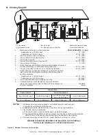
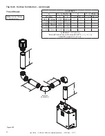
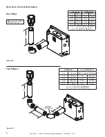
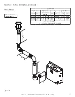
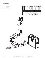
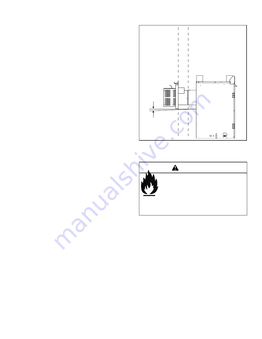
F. Vent Diagrams
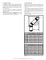
Figure 4.8 Vent Cap - Generic Appliance Shown
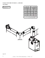
General Rules:
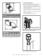
• SUBTRACT 3 ft. (914 mm) from the total H measurement
for each 90º elbow installed horizontally.
• SUBTRACT 1-1/2 ft. (457 mm) from the total H
measurement for each 45º elbow installed horizontally.
• A maximum of three 90º elbows (or six 45º elbows) may
be used in any vent configuration. Some elbows may be
installed horizontally. See Figure 4.15.
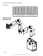
• Elbows may be placed back to back anywhere in the
system.
•
Any 90º elbow may be replaced with two back to back
45º elbows.
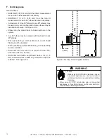
• When penetrating a combustible wall, a wall shield
firestop must be installed.
• When penetrating a combustible ceiling, a ceiling firestop
must be installed.
• Horizontal runs of vent do not require vertical rise;
horizontal runs may be level.
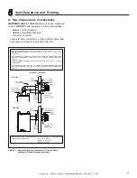
• Horizontal termination cap should have a 1/4 in. (6
mm) downward slant to allow any moisture in cap to be
released. See Figure 4.8.
W
A
LL
1/4 in. max.
(6 mm)
Fire Risk.
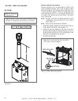
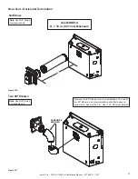
• When using SLP-HRC-SS termination cap on
top vented appliances, a one foot minimum
vertical vent section is required before installing
first elbow.
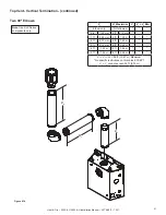
• When using DVP-TB1 termination cap on top vented
appliances, a three foot minimum vertical vent section is
required before installing first elbow.
WARNING


