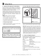
background image

19

Heat & Glo  •  350X-AU, 550X-AU Installation Manual  •  2279-980


•  12/17

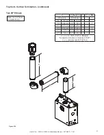
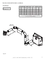
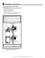
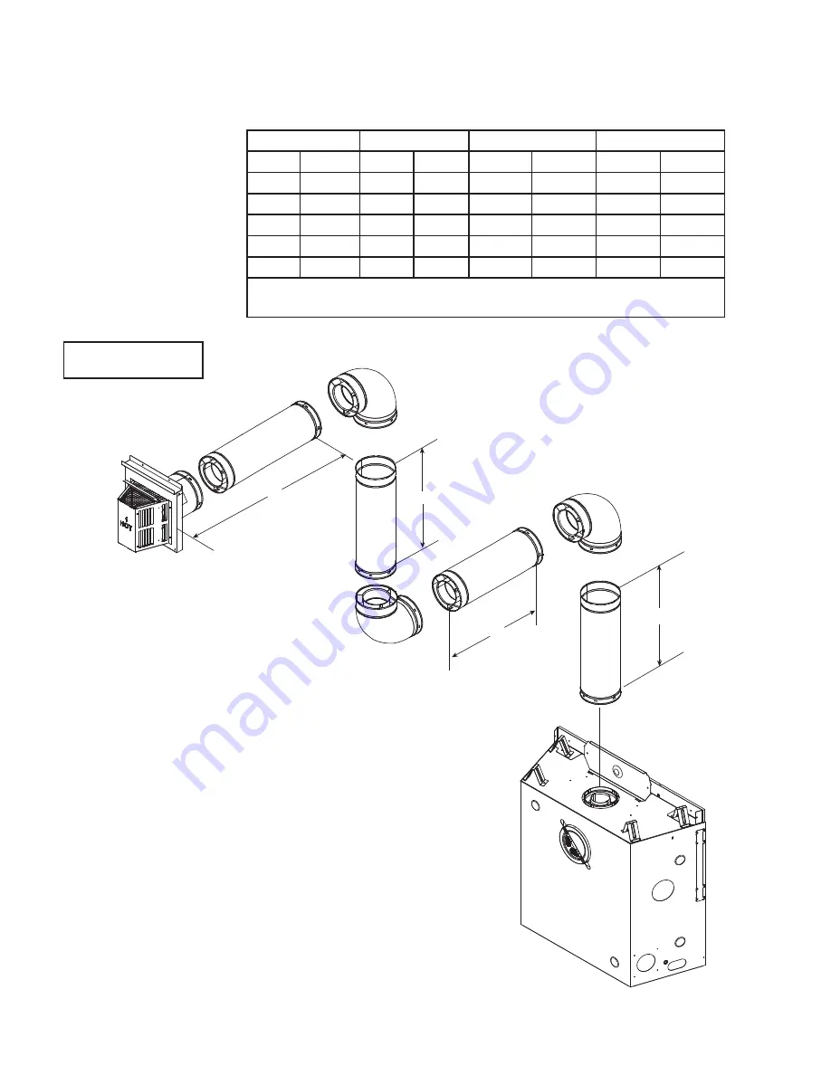
Figure 4.11

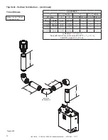
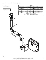
Top Vent - Horizontal Termination  - (continued)

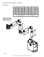
Three Elbows

Note

: Use SLP Series 

components only.

H

2

H

1

V

2

V

1

V

1

 Min.

H

1

 Max.

V

2

 Min.

H

2

 Max.

6 in.

 152 mm

1 ft.

305 mm

1 ft.

305 mm

1 ft.

305 mm

1 ft.

305 mm

2 ft.

610 mm

2 ft.

610 mm

2 ft.

610 mm

2 ft.

610 mm

2 ft.

610 mm

3 ft.

914 mm

4 ft.

1.22 m

3 ft.

914 mm

3 ft.

914 mm

4 ft.

1.22 m

6 ft.

1.83 m

4 ft.

1.22 m

4 ft.

1.22 m

5 ft.

1.52 m

8 ft.

2.44 m*

5 ft.

1.52 m

6 ft.*

1.83 m

6 ft.

1.83 m

6 ft.

1.83 m

*H

1

 = 6 ft. (1.83 m) Maximum   *H

1

 + H

2

 = 12 ft. (3.66 m) Maximum  

V

1

 + V

2

 = 32 ft. (9.75 m) Maximum    V

1

 + V

2

 + H

1

 + H

2

 = 36 ft. (10.97 m) Maximum

Summary of Contents for 350X-AU

Page 1: ...her flam mable vapors and liquids in the vicinity of this or any other appliance What to do if you smell gas DO NOT try to light any appliance DO NOT touch any electrical switch DO NOT use any phone in your building Leave the building immediately Immediately call your gas supplier from a neighbor s phone Follow the gas sup plier s instructions If you cannot reach your gas supplier call the fire de...

Page 2: ...s 14 E Measuring Standards 15 F Vent Diagrams 16 5 Vent Clearances and Framing A Pipe Clearances to Combustibles 29 B Wall Penetration Framing Firestops 30 C Ceiling Firestop Floor Penetration Framing 31 D Install Attic Insulation Shield 31 6 Appliance Preparation A Vent Collar Preparation 32 B Installing the Optional Heat Zone 240V Kit 34 C Securing and Leveling the Appliance 34 D Non Combustible...

Page 3: ...y installed ___________________________ Gas Section 9 Pg 41 43 Proper appliance for fuel type ___________________________ Was a conversion performed ___________________________ Leak check performed and inlet pressure verified ___________________________ Verified proper air shutter setting for installation type ___________________________ Finishing Section 10 Pg 47 49 Combustible materials not inst...

Page 4: ...ane Butane 2 37 2 61 kPA D Gas Pressure Requirements E High Altitude Installations NOTICE If the heating value of the gas has been reduced these rules do not apply Check with your local gas utility or authorities having jurisdiction When installing above 2000 ft 610 m elevation Reduce input rate 4 for each 1000 ft 305 m above 2000 ft 610 m F Non Combustible Materials Specification Material which w...

Page 5: ...mb line Safety glasses Level Reciprocating saw Flat blade screwdriver Non corrosive leak check solution 1 2 3 4 in 13 19 mm length 6 or 8 Self drilling screws Caulking material 300 ºF 149 ºC minimum continuous exposure rating Improper installation adjustment alteration service or maintenance can cause injury or property damage For assistance or additional information consult a qualified service te...

Page 6: ... safe operation DO NOT install damaged in complete or substitute components Keep appliance dry Hearth Home Technologies disclaims any responsibility for and the warranty will be voided by the following actions Installation and use of any damaged appliance or vent system component Modification of the appliance or vent system Installation other than as instructed by Hearth Home Technologies Improper...

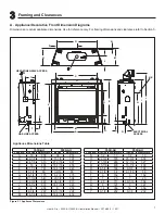
Page 7: ...U 550X AU Location Inches Millimeters Inches Millimeters A 33 838 36 914 B 28 1 8 714 31 1 8 791 C 24 1 8 613 27 3 16 691 D 16 406 18 1 16 459 E 31 1 8 791 33 1 16 840 F 3 1 2 89 3 9 16 90 G 6 7 8 175 6 7 8 175 H 21 3 8 543 23 3 8 594 I 32 3 8 822 34 3 8 873 J 34 1 2 876 36 7 16 926 K 8 203 8 203 L 8 3 4 222 8 13 16 224 M 16 1 4 413 16 5 16 414 350X AU 550X AU Location Inches Millimeters Inches Mi...

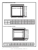
Page 8: ... C A D B E F G A B C D E F G 550X AU CF 32 in 26 9 16 18 11 16 30 13 16 23 5 16 25 7 16 3 1 2 4 9 16 mm 675 475 783 592 646 89 116 CLEAN FACE DECORATIVE FRONT A B C D E F G 350X AU FS 3 in 26 23 28 1 5 8 2 5 8 25 1 16 26 3 4 mm 660 584 711 41 67 637 680 550X AU FS 5 in 28 7 8 25 1 8 31 1 5 8 2 5 8 27 1 8 28 3 4 mm 733 638 787 41 67 689 730 A B F G E D C ...

Page 9: ...dividual design preference Figure 3 3 Appliance Locations J C A K H B F D I I F A E G L Refer to Section 10 B for mantel and wall projection information Consider the mantel or cabinet system to be installed and comply with the necessary requirements for elevated hearth Refer to instructions included with cabinet system Models A B C D E Min F G H I J K L 350X AU in 39 1 2 34 55 7 8 See Section 10 B...

Page 10: ... Combustible Floor Combustible Flooring Behind Appliance Sides of Appliance Front of Appliance Rough Opening Width Rough Opening Width Rough Opening Depth Rough Opening Depth 350X AU in 10 8 5 8 32 3 4 16 1 4 16 1 4 34 32 0 0 1 2 1 2 36 mm 254 219 832 413 413 864 813 0 0 13 13 914 550X AU in 10 8 5 8 34 3 4 16 1 4 16 1 4 37 32 0 0 1 2 1 2 36 mm 254 219 882 413 413 940 813 0 0 13 13 914 Adjust fram...

Page 11: ...air infiltration may be an issue the inside surfaces may be sheetrocked and taped or an equivalent method may be used to achieve maximum air tightness To further prevent drafts the wall shield and ceiling firestops should be caulked with caulk with a minimum of 300 ºF 149 C continuous exposure rating to seal gaps Gas line holes and other openings should be caulked with caulk with a minimum of 300 ...

Page 12: ...ith the decorative cap cover A B 6 in minimum up to 20 in 152 mm 508 mm 18 in minimum 457 mm 20 in and over 0 in minimum In a staggered installation with both gas and wood or fuel oil terminations the wood or fuel oil termination cap must be higher than the gas termination cap Figure 4 1 Minimum Height From Roof To Lowest Discharge Opening H MIN MINIMUM HEIGHT FROM ROOF TO LOWEST DISCHARGE OPENING...

Page 13: ... T a Below eaves balconies or other projections MIN CLEARANCE in mm Appliances up to 50 MJ h input 12 300 Appliances over 50 MJ h input 20 1 2 500 b From the ground or above a balcony 12 300 c From a return wall or external corner 20 1 2 500 d From a gas meter M 39 1000 e From an electricity meter or fuse box P 20 1 2 500 f From a drain or soil pipe 6 150 g Horizontally from any building structure...

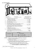
Page 14: ...t See Figure 4 4 Two 45º elbows may be used in place of one 90º elbow On 45º runs one foot of diagonal is equal to 8 1 2 in 216 mm horizontal run and 8 1 2 in 216 mm vertical run A length of straight pipe is allowed between two 45º elbows See Figure 4 4 Figure 4 5 shows the vertical and horizontal offsets for DVP or SLP elbows Figure 4 4 HORIZONTAL VERTICAL RUN RISE E F F E C T I V E L E N G T H D...

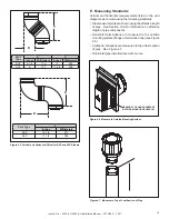
Page 15: ...t diagrams were made using the following standards Pipe measurements are shown using the effective length of pipe See Section 12 A for information on effective length of pipe components Horizontal terminations are measured to the outside mounting surface flange of termination cap see Figure 4 6 Vertical terminations are measured to top of last section of pipe See Figure 4 7 Horizontal pipe install...

Page 16: ...ay be replaced with two back to back 45º elbows When penetrating a combustible wall a wall shield firestop must be installed When penetrating a combustible ceiling a ceiling firestop must be installed Horizontal runs of vent do not require vertical rise horizontal runs may be level Horizontal termination cap should have a 1 4 in 6 mm downward slant to allow any moisture in cap to be released See F...

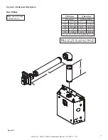
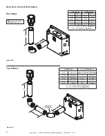
Page 17: ...Use SLP Series components only H1 V1 Note A 6 in 152 mm section of straight flue must be attached to the heater before a 90 elbow V1 Minimum H1 Maximum Elbow only NOT ALLOWED 1 ft 305 mm 2 ft 610 mm 2 ft 610 mm 4 ft 1 22 m 3 ft 914 mm 8 ft 2 44 m 4 ft 1 22 m 10 ft 3 05 m 5 ft 1 52 m 16 ft 4 88 m V1 H1 30 ft 9 14 m Maximum ...

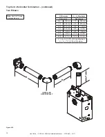
Page 18: ...e SLP Series components only INSTALLED HORIZONTALLY H1 H2 V1 V1 Minimum H1 H2 Maximum Elbow only Not allowed 6 in 152 mm 1 ft 305 mm 1 ft 305 mm 2 ft 610 mm 2 ft 610 mm 4 ft 1 22 m 3 ft 914 mm 6 ft 1 83 m 4 ft 1 22 m 8 ft 2 44 m 5 ft 1 52 m 10 ft 3 05 m 20 ft 6 10 m 10 ft 3 05 m V1 H1 H2 30 ft 9 14 m Maximum H1 H2 10 ft 3 05 m Maximum ...

Page 19: ... Max 6 in 152 mm 1 ft 305 mm 1 ft 305 mm 1 ft 305 mm 1 ft 305 mm 2 ft 610 mm 2 ft 610 mm 2 ft 610 mm 2 ft 610 mm 2 ft 610 mm 3 ft 914 mm 4 ft 1 22 m 3 ft 914 mm 3 ft 914 mm 4 ft 1 22 m 6 ft 1 83 m 4 ft 1 22 m 4 ft 1 22 m 5 ft 1 52 m 8 ft 2 44 m 5 ft 1 52 m 6 ft 1 83 m 6 ft 1 83 m 6 ft 1 83 m H1 6 ft 1 83 m Maximum H1 H2 12 ft 3 66 m Maximum V1 V2 32 ft 9 75 m Maximum V1 V2 H1 H2 36 ft 10 97 m Maxi...

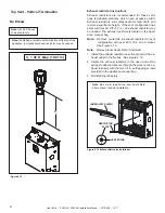
Page 20: ...e vent configuration has a total vertical of 12 ft 3 7 m an exhaust restrictor may be needed The exhaust restrictor is located in the appli ance manual bag Note Remove center tab in exhaust restrictor for vent configuration with over 20 ft 6 0 m of vertical See Figure 4 13 Note Remove inner heat shield if installed 1 Install the exhaust restrictor over the center of the ex haust outlet in the fire...

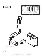
Page 21: ...ical Termination continued H1 V1 V2 V1 H1 Maximum V2 V1 V2 Min Elbow only Not allowed 6 in 152 mm 2 ft 610 mm 1 ft 305 mm 4 ft 1 22 m 2 ft 610 mm 6 ft 1 83 m 3 ft 914 mm 8 ft 2 44 m 4 ft 1 22 m 12 ft 3 66 m 5 ft 1 52 m 16 ft 4 88 m V1 V2 H1 36 ft 10 97 m Maximum No specific restrictions on this value EXCEPT V1 V2 cannot exceed 32 ft 9 75 m ...

Page 22: ...Minimum 90º Elbow 0 0 1 1 2 ft 457 mm 1 1 2 ft 457 mm 1 2 ft 152 mm 1 ft 305 mm 1 1 2 ft 457 mm 2 ft 610 mm 2 1 2 ft 762 mm 4 ft 1 2 m 3 1 2 ft 1 1 m 6 ft 1 8 m 4 1 2 ft 1 4 m 14 ft 4 3 m H1 Maximum 14 ft 4 3 m No specific restrictions on this value EXCEPT V1 V2 H1 H2 CANNOT exceed 40 ft 12 2 m Note Use SLP Series components only INSTALLED HORIZONTALLY H1 H2 V1 V2 ...

Page 23: ...DELS H1 18 in 457 mm Maximum Note Use DVP Series components only H1 90 DEGREE ELBOWS Must use two 90º elbows for corner installations The use of two 90º elbows in a corner installation will affect space re quirements See Section 3 B Use of 45º elbow not allowed Two 90º Elbows Note Use DVP Series components only Figure 4 17 ...

Page 24: ... H1 H2 Maximum 6 in 152 mm Back to Back 90º Elbows 6 in 152 mm 1 ft 305 mm 6 in 152 mm 6 in 152 mm 1 ft 305 mm 1 1 2 ft 457 mm 1 ft 305 mm 1 ft 305 mm 1 ft 305 mm 2 ft 610 mm 2 ft 610 mm 2 ft 610 mm 2 ft 610 mm 4 ft 1 22 m 3 ft 914 mm 3 ft 914 mm 4 ft 1 22 m 8 ft 2 44 m 4 ft 1 22 m 4 ft 1 22 m 6 ft 1 83 m 10 ft 3 05 m V1 H1 H2 30 ft 9 14 m Maximum H1 4 ft 1 22 m Maximum H1 H2 10 ft 3 05 m Maximum ...

Page 25: ... Minimum H2 H3 H1 H2 H3 Max 0 ft 0 mm Back to Back 90º Elbows 1 ft 305 mm 1 ft 305 mm 6 in 152 mm 6 in 152 mm 1 ft 305 mm 1 1 2 ft 457 mm 1 ft 305 mm 1 ft 305 mm 1 ft 305 mm 2 ft 610 mm 2 ft 610 mm 2 ft 610 mm 2 ft 610 mm 4 ft 1 22 m 3 ft 914 mm 3 ft 914 mm 5 ft 1 52 m 8 ft 2 44 m 4 ft 1 22 m 4 ft 1 22 m 6 ft 1 83 m 10 ft 3 05 m V1 H1 H2 H3 30 ft 9 14 m Maximum H1 4 ft 1 22 m Maximum H1 H2 H3 10 f...

Page 26: ...only V1 Minimum H1 Maximum 1 ft 305 mm 3 ft 914 mm 2 ft 610 mm 6 ft 1 83 m 3 ft 914 mm 8 ft 2 44 m 4 ft 1 22 m 11 ft 3 35 m 5 ft 1 52 m 12 ft 3 66 m V1 H1 36 ft 10 97 m Maximum H1 12 ft 3 66 m Maximum V1 Minimum H1 H2 Maximum 2 ft 610 mm Back to Back 90º Elbows 1 ft 310 mm 2 ft 610 mm 2 ft 610 mm 4 ft 1 22 m 3 ft 914 mm 7 ft 2 13 m 4 ft 1 22 m 9 ft 2 74 m V1 H1 32 ft 9 75 m Maximum H1 H2 9 ft 2 74...

Page 27: ...Maximum V1 Minimum H2 H1 H2 Maximum 1 1 2 ft 457 mm Back to Back Elbows 1 ft 305 mm 2 1 2 ft 762 mm 3 1 2 ft 1 1 m 1 ft 305 mm 3 ft 914 mm 6 1 2 ft 2 0 m 5 1 2 ft 1 2 m 2 ft 610 mm 5 ft 1 5 m 10 1 2 ft 3 2 m 7 1 2 ft 2 3 m 3 ft 914 mm 7 ft 2 1 m 14 1 2 ft 4 4 m H1 Maximum 7 1 2 ft 2 3 m V1 V2 H1 H2 Maximum 40 ft 12 2 m Note Use DVP Series components only ...

Page 28: ...H1 H2 H3 V1 Minimum H1 H2 H3 Maximum 8 ft 2 44 m 6 ft 1 83 m 9 ft 2 74 m 7 ft 2 13 m 10 ft 3 05 m 8 ft 2 44 m 10 ft 3 05 m 8 ft 2 44 m V1 H1 H2 H3 32 ft 9 75 m Maximum No specific restrictions on this value EXCEPT V1 H1 H2 H3 cannot exceed 32 ft 9 75 m Maximum H1 H2 H3 8 ft 2 44 m Maximum Note Use DVP Series components only ...

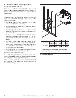
Page 29: ...ST overlap by a minimum of 1 1 2 in 38 mm DVP heat shield designed to be used on a wall 4 in to 7 1 4 in 102 mm to 184 mm thick If wall thickness is less than 4 in 102 mm the existing heat shields must be field trimmed If wall thickness is greater than 7 1 4 in 184 mm a DVP HSM B will be required SLP heat shield designed to be used on a wall 4 3 8 in to 7 5 8 in 111 mm to 194 mm thick If wall thic...

Page 30: ...d on all four sides using the same size framing materials as those used in the wall construction SLP pipe A wall shield firestop must be placed on each side of an interior wall A minimum 1 1 2 in 38 mm overlap of attached heat shields must be main tained DVP pipe A wall shield firestop is required on one side only on interior walls If your local inspector re quires a wall shield firestop on both s...

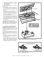
Page 31: ...ulation must be kept back from the pipe to prevent overheating Figure 5 3 Installing Ceiling Firestop Generic Appliance Shown Figure 5 4 Installing the Attic Shield INSTALL ATTIC INSULATION SHIELDS BEFORE OR AFTER INSTALLATION OF VENT SYSTEM CEILING FIRESTOP INSTALLED BELOW CEILING CEILING FIRESTOP INSTALLED ABOVE CEILING ATTIC ABOVE A PIPE DVP SLP A 10 in 254 mm 9 in 229 mm A D Install Attic Insu...

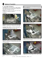
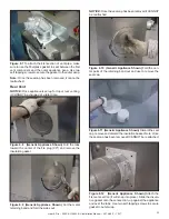
Page 32: ...cal position as shown above The heat shield must remain in the vertical position Figure 6 1 For top vent remove the two screws holding the top heat shield in place For rear vent see next page 2 SCREWS 2 SCREWS Figure 6 3 Replace the two screws as shown WARNING Risk of Fire Do not remove heat shield El evated header temperatures may cause a fire Figure 6 4 Remove the seal cap Figure 6 5 Remove the ...

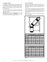
Page 33: ...use to remove the seal cap Figure 6 11 GenericAppliance Shown Discard the seal cap remove and discard the insulation basket Note Once the seal cap has been removed it CANNOT be reattached Figure 6 12 Generic Appliance Shown Attach the first vent section it will snap into place Slide the insula tion gasket onto the vent section up against the appliance and over the tabs Use two self tapping screws ...

Page 34: ...o use wood shims underneath the appliance Place a level on top sides and bottom as shown in Figure 6 14 Secure the appliance to the framing by using nails or screws through the nailing tabs Optional Secure the appliance to the floor by inserting two screws through the pilot holes at the bottom of the appliance WARNING Risk of Fire DO NOT remove factory in stalled non combustible material A non com...

Page 35: ...ating Use screws no longer than 1 2 in 13 mm If predrilling screw holes DO NOT penetrate inner pipe WARNING Risk of Fire or Explosion DO NOT break silicone seals on slip sections Use care when remov ing termination cap from slip pipe If slip section seals are broken during removal of the termination cap vent could leak Figure 7 4 Seams Note Make sure that the seams are not aligned to prevent unint...

Page 36: ...mmended that the tape seam is positioned on the bottom side of the vent pipe Only outer pipes need to be sealed All appliance collar pipe slip section elbow and cap outer flues shall be sealed in this manner unless otherwise stated Figure 7 5 Adding Venting Components WARNING Risk of Fire or Explosion DO NOT break silicone seals on slip sections Use care when remov ing termination cap from slip pi...

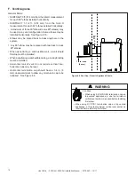
Page 37: ...every 8 ft 2 44 m after the maximum allowed 25 ft 7 62 m of unsupported rise Vertical runs originating off the rear of the appliance or after any elbow must be supported every 8 ft 2 44 m Horizontal runs must be supported every 5 feet 1 52 m Vent supports or plumbers strap spaced 120º apart may be used to support vent sections See Figures 7 8 and 7 9 Wall shield firestops may be used to provide ho...

Page 38: ...Assemble and Install Storm Collar CAUTION Risk of Cuts Abrasions or Flying Debris Wear protective gloves and safety glasses during instal lation Sheet metal edges are sharp Slide the storm collar onto the exposed pipe section and align brackets Insert a bolt provided through the brackets and install nut Do not completely tighten Slide the assembled storm collar down the pipe section until it rests...

Page 39: ...extended heat shield must be used If the wall thickness is less than 4 in 102 mm DVP or 4 3 8 in 111 mm SLP the heat shields on the cap and wall shield firestop must be trimmed A minimum 1 1 2 in 38 mm overlap MUST be maintained Use an extended heat shield if the finished wall thickness is greater than 7 1 4 in 184 mm The extended heat shield may need to be cut to length maintaining sufficient len...

Page 40: ...igure 7 16 Venting Through the Wall Generic Appliance Shown INTERIOR HEAT SHIELD OR EXTENDED HEAT SHIELD WALL SHIELD FIRESTOP HEAT SHIELD 1 1 2 IN 38 MM MIN OVERLAP SHEATHING VENT DEPTH FROM BACK OF APPLIANCE TO OUTSIDE SURFACE OF EXTERIOR WALL SEE CHART BELOW SLIP SECTION CAN BE EXTENDED INNER VENT OUTER VENT EXTERIOR Note When using termination caps with factory supplied heat shield attached no ...

Page 41: ...e wall box 8 Electrical Information Electrical Service and Repair WARNING Risk of Shock Label all wires prior to dis connection when servicing controls Wiring errors can cause improper and dangerous operation Verify proper operation after servicing WARNING Risk of Shock Replace damaged wire with type 105 ºC rated wire Wire must have high temperature insulation Accessories Requirements This applian...

Page 42: ...e 6 volt transformer plug into the appliance junction cord to supply power to the appliance OR install 4AA cell batteries not included into the battery pack before use B Wiring Requirements NOTICE Batteries should only be used as a power source in the event of an emergency power outage Batteries should not be used as a primary long term power source Battery polarity must be correct when installing...

Page 43: ... done by a qualified service technician Placement of this remote control may affect performance An assessment of the space should be done prior to in stallation for optimum performance Determine Location Determine the location for the remote control The selected location should be in the same space as the appliance Never place this unit in a separate room The remote control must be placed within 3...

Page 44: ...40 kPa 2 40 kPa Fire Risk Explosion Hazard High pressure will damage valve Disconnect gas supply piping BEFORE pressure testing gas line at test pressures above 1 2 psig Close the manual shutoff valve BEFORE pressure testing gas line at test pressures equal to or less than 1 2 psig WARNING D High Altitude Installations NOTICE If the heating value of the gas has been reduced these rules do not appl...

Page 45: ... wing nut shown in Figure 9 1 Push Slide the wing nut toward the back of the appliance to close the shutter Pull Slide the wing nut toward the front of the appliance to open the air shutter Air shutter settings should be adjusted by a qualified ser vice technician at the time of installation Factory Pre Set Air Shutter Settings E Air Shutter Setting NOTICE Flames should not appear orange or stretc...

Page 46: ...d for identification and veri fication purposes This task should be performed by a qualified service technician The logs and burner must be removed to see these identification marks Disconnect the pilot from the burner before removal See Figure 9 2 for burner identification chart Notch patterns are located on bottom side of burner Figure 9 2 Burner Identification ...

Page 47: ...ng into the glass opening Observe all clearances when applying combustible materials Confirm that appliance is plum square and level See Section 6 Seal joints between the finished wall and appliance top and sides using a 300 ºF 149 C minimum sealant Refer to Figure 10 1 WARNING Risk of Fire DO NOT apply combustible materials beyond the minimum clearances Comply with all minimum clearances to combu...

Page 48: ...W 5 7 8 in 149 mm MINIMUM 3 in 76 mm MINIMUM APPLIANCE OPENING See Dimension B on Appliance Dimension Diagram Figure 3 1 Figure 10 5 Wall Projection acceptable on one side of opening Note Clearance from opening to perpendicular wall Non Combustible Mantels Figure 10 3 Minimum Vertical and Maximum Horizontal Dimensions of Non Combustibles Figure 10 2 Minimum Vertical and Maximum Horizontal Dimensio...

Page 49: ... what kind of decorative front and finishing material is going to be used on the appliance use the information below which shows the decorative front models and the non combustible finishing material thickness allowed Inside Fit Firescreen Front 1 4 in 0 102 mm Finishing Note Refer to Section 3 for individual decorative front dimensions as installed on appliance Flush Mounting Firescreen Front 20 ...

Page 50: ...ll valve before in stalling the splatter guard to prevent accidental lighting Remove the splatter guard before lighting the appliance Pull the four glass assembly latches out of the groove on the glass frame Remove glass assembly from the appliance See Figure 11 1 GLASS ASSEMBLY LATCHES BOTH BOTTOM AND TOP D Setup Overview These are common log and refractory instructions for the 350X AU and 550X A...

Page 51: ...for fogging tips Prior to painting take precautions to prevent any overspray from reaching the pilot assembly Paint is not included with the appliance See Fig 11 3 Fogging Tips Apply paint with the ember lights turned on This will help avoid over fogging or under fogging Reduce the lighting in the room while applying the paint Fog the Teco Sil to create a realistic coal bed appear ance Allow the p...

Page 52: ... Figure 1 Log Pin and Glowing Ember Locations Figure 2 Example of Log Pin Holes Log Placement Tips The rear left log rear right log and small burner log utilize holes in the bottom side of the logs that correspond to the log pins on the burner Reference Figure 1 and Figure 2 Additionally the rear left log and rear right log are located by indentations in the right and left hearth components See Fi...

Page 53: ...odels it may be necessary to lift the rear left log slightly to install the rear right log The right side of the log will reside within the indentation in the right hearth component See Figure 5 350X AU Models The rear right log will be posi tioned to maintain about a 2 in 51 mm rear gap between the rear right log and the back wall The rear right log will maintain a 3 4 in 19 mm gap from the right...

Page 54: ...nstalled Figure 8 Location of Right Log Indentation 5 Remove top left log from packaging Place the log into the indentation on the rear left log The Y shaped end of the log will rest on the ember tray and the Te co Sil rock See Figure 7 and Figure 8 Figure 7 Location of Left Log indentation INDENTATION LEFT LOG Figure 9 Top Right Log Installed Log Set Complete 6 Remove top right log from packaging...

Page 55: ...nspect the gasket to ensure it is undamaged and inspect the glass for cracks chips or scratches DO NOT strike slam or scratch glass DO NOT operate appliance with glass removed cracked broken or scratched Replace as a complete assembly Replacing Fixed Glass Assembly Replace the glass door on the appliance Pull out and latch the four glass assembly latches into the groove on the glass frame GLASS AS...

Page 56: ...0 1 2 in 267 mm 10 7 8 in 276 mm 45 7 3 8 in 187 mm 11 3 8 in 289 mm 1 1 4 in 32 mm 9 1 4 in 235 mm 13 1 4 in 337 mm 1 2 in TYP DVP90ST 90 Elbow 10 in 254 mm 10 in 254 mm 1 in 25 mm 12 in 305 mm 14 in 356 mm 1 in 25 mm 8 in 203 mm 6 in 152 mm 10 in 254 mm 1 1 2 in 38 mm 5 in 127 mm 12 in 305 mm UP DVP HVS Vent Support DVP WS Wall Shield Firestop DVP FS Ceiling Firestop DVP45 45º Elbow DVP Pipe see...

Page 57: ... mm The heat shield is designed to be used on a wall 4 in to 7 1 4 in 102 mm to 184 mm thick If wall thickness is less than 4 in 102 mm the existing heat shields must be field trimmed If wall thickness is greater than 7 1 4 in 184 mm a DVP HSM B will be required Heat Shield 1 in 25 mm 14 in 356 mm 3 8 in 10 mm 1 in 25 mm 7 1 4 in 184 mm 7 3 4 to 10 3 8 in 197 to 264 mm DVP FBHT FireBrickTerminatio...

Page 58: ...n is required before installing first elbow WARNING RF6M Roof Flashing Multi pak 13 in 330 mm 15 in 381 mm 8 1 8 in 206 mm 10 7 8 in 276 mm 10 1 2 in 267 mm 3 87 Effective Length 5 3 4 to 8 3 8 in 146 to 213 mm 5 1 2 in 140 mm 8 3 8 in 213 mm 31 in 787 mm 24 5 8 in 625 mm 13 1 4 in 367 mm RF12M Roof Flashing Multi pak 7 1 4 in 184 mm 12 in 305 mm 5 1 4 in 133 mm 12 1 2 in 318 mm DVP TVHW VerticalTe...

Page 59: ... in 251 mm 6 1 2 in 165 mm 9 1 4 in 235 mm SLP45 45 Elbow SLP 90ST 90 Elbow Effective Height Length SLP PIPE SLP HVS Horizontal Pipe Support SLP FS Ceiling Firestop SLP WS Wall Shield Firestop DVP SLP24 Adapter Effective Height Length Pipe inches mm SLP4 4 102 SLP6 6 152 SLP12 12 305 SLP24 24 610 SLP36 36 914 SLP48 48 1219 SLP6A 2 6 51 152 SLP12A 2 12 51 305 Figure 12 4 SLP Series Vent Components ...

Page 60: ...M B will be required Heat Shield Term Cap Minimum Effective Length Maximum Effective Length Trap1 3 1 8 in 4 3 4 in 79 mm 121mm Trap2 5 1 4 in 9 1 4 in 133 mm 235 mm 8 in 203 mm 12 in 305 mm Max Effective Length 14 7 16 in 367 mm 14 7 16 in 367 mm 2 5 16 in 59 mm 3 15 16 in 101 mm 6 11 16 in 169 mm 8 in 203 mm 3 15 16 in 101 mm 3 13 16 in 97 mm 5 1 16 in 128 mm 6 3 8 in 163 mm 4 3 16 in 106 mm 4 5...

Page 61: ...12 1 2 in 318 mm 12 in 305 mm SLP CCS BK Cathedral Ceiling Support Box Black SLP DCF BK Ceiling Firestop Black SLK SNKD Snorkel Termination Cap SLP TVHW Vertical Termination Cap 13 1 2 in 343 mm 28 1 2 in 724 mm 10 11 16 in 271mm 4 3 4 in 121 mm 4 1 8 in 105 mm A Vent Components Diagrams continued Figure 12 6 SLP Series Vent Components ...

Page 62: ...Zone 240V Kit Follow the instruction supplied with the kit for operation Preparation of the appliance for installation of the kit is discussed in Section 6 B Contact your dealer if you have questions Printed in U S A Copyright 2017 Heat Glo a brand of Hearth Home Technologies 7571 215th Street West Lakeville MN 55044 www heatnglo com Please contact your Heat Glo dealer with any questions or concer...

Reviews: