12
Installation and Operation Manual
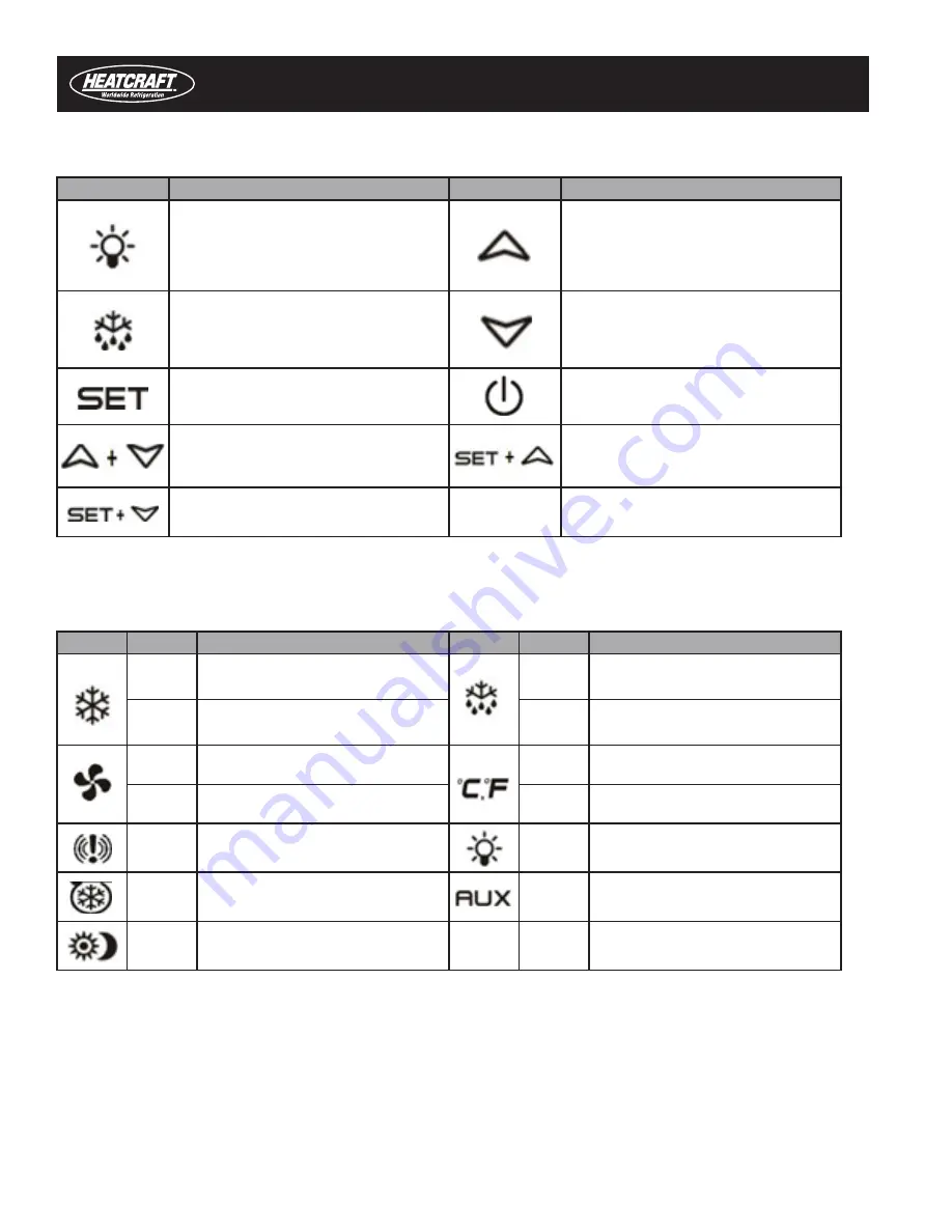
There are 6 keys on the control front panel display. Table 6-1 explains their meaning.
Key
Function
Key
Function
Switches the light ON and OFF, if oA1 = Lig
Press the UP-arrow key to see the
MAX stored temperature, to browse the
parameter codes in programming mode,
or to increase the displayed temperature
value.
Starts a manual defrost
Press the DOWN arrow key to see the
MIN temperature, to browse the parameter
codes in programming mode, or to
decrease the displayed temperature value.
Press to display target setpoint, to select a
parameter in programming mode, or to con-
firm an operation
Switches the device ON and OFF, if
onF
= oFF
Locks/Unlocks the keyboard
Returns to room temperature display
Enter programming mode
Each LED icon and its mode are described in Table 6-2.
Icon
Mode
Mode
Icon
Mode
Mode
On
Compressor enabled
On
Defrost enabled
Flashing
Anti-short cycle delay enabled
Flashing
Drip time in progress
On
Fans enabled
On
Measurement unit in centigrade (°C)
or Fahrenheit (°F)
Flashing
Fans delay after defrost in progress
Flashing
Programming phase
ON
An alarm is occurring
ON
Light On
ON
Energy saving enabled
ON
Auxiliary relay ON
ON
Energy saving enabled
6.2. Common User Operations
This section covers common user operations. Common user operations include:
•
Changing a setpoint value
•
Changing a parameter value
•
Moving parameters to and from the user level and hidden menu
•
Starting a manual defrost
•
Viewing the minimum and maximum temperatures
Table 6-1. Front Panel Keys and Functions
Table 6-2. Icons and Their Meanings


