4
Installation and Operation Manual
2.1. Components
Electrical
All field installed wiring must comply with the NATIONAL ELECTRICAL CODE AND LOCAL ELECTRICAL CODES.
The merchandiser is provided with power cord(s) that have a male plug that is shipped loose for installation in the
store. There is/are also matching female receptacle(s) that are shipped loose. To gain access to the inside of the
electrical control panel, remove the control panel cover. Ensure that the correct input voltage is being supplied to the
merchandiser.
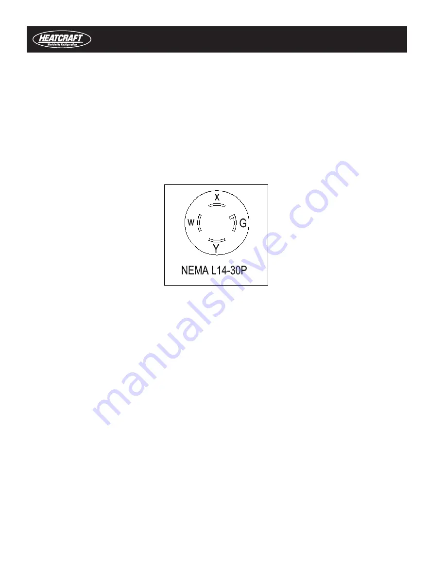
The power supply for each system is 4 wire 208 VAC that includes two 208 VAC hot legs, a neutral wire and a ground
wire (Figure 2-2). All 10 foot models have two separate refrigeration systems with two separate power supplies.
WARNING!
ALL MERCHANDISERS MUST BE PROPERLY GROUNDED
Ensure that the proper wire conductor size and branch circuit protection are employed on each
electrical circuit for safe operation.
Evaporator Fan Motor
The evaporator fan motor is permanently oiled for the life of the motor and requires no periodic maintenance. The fan
motor is wired according to the wiring diagram and must run continuously to circulate air through the evaporator coil
and air ducts during defrost to remove frost and ice that has accumulated during the refrigeration cycle.
Anti-Condensate Heaters
Anti-condensate heaters are installed in the merchandiser to prevent surface condensation or frost from forming
on specific areas of the merchandiser. All insulated glass assemblies contain three 3/16" thick glass panels with
two 1/4" air spaces in between the glass panels. Heat is applied on the inside surface of the exterior pane of each
insulated glass assembly. Anti-condensate heaters are energized only when the merchandiser is operated in the low
temperature mode.
Defrost Heater
A standard 115 volt defrost heater is located inside the fan plenum and is attached to the front face of the evaporator
coil. The defrost heater is designed to provide evenly distributed heat to the evaporator coil to ensure adequate
defrosting of the evaporator coil during defrost cycles. The defrost cycle is time initiated by the electronic controller
Figure 2-2. Receptacle for Four-Wire 208 VAC


