background image

14

Installation and Operations Manual

WARNING:

 When first connected, easy is already on and 

ready to be used. The instrument can be switched on from 

a supervisor PC and via an external contact (setting A4= 

5). The latter has priority over the other modes.

SET POINT SETTING (DESIRED TEMPERATURE VALUE)
The easy and easy compact devices control the desired temperature 
(set point) inside the cabinet or cold room directly and dynamically.
To view and modify the set point:

•  press SET for 1 s, the set value will start flashing;
•  increase or decrease the value using UP or DOWN;
•  press SET to confirm the new value.

MANUAL DEFROST
Press  DOWN  for  more  than  3  s  (activated  only  if  the  temperature 
conditions are right).
CONTINUOUS CYCLE
Press UP+DOWN for more than 3 s (activated only if the temperature 
conditions are right).
The continuous cycle is used to maintain refrigeration active in the 
cabinet or cold room, regardless of the temperature inside the unit. 
This may be useful for rapidly bringing the temperature below the 
set point value.
RAPID DISPLAY OF THE TEMPERATURE READ BY THE OTHER 

PROBES
Press  the  DOWN  button  to  scroll  the  temperatures  read  by  the 
probes.  Each  time  the  DOWN  button  is  pressed,  the  display  will 
show  the  name  of  the  probe  Pr1,  Pr2  or  Pr3  (only  on  the  models 
with 3 inputs and with multifunction input configured as a probe) 
and after 1 s the temperature measured by the selected probe will 
be displayed.
To display the other probes, press DOWN again.
To  return  to  the  normal  display,  wait  3  s  without  pressing  any 
buttons (exit by timeout).

Temperature Display

The  temperature  displayed,  the  unit  of  measure  and  the  decimal 
resolution can be set according to the following parameters: /4, /5 
and /6.

/4 : select probe displayed
Used  to  choose  whether  to  display  the  temperature  read  by  the 
control probe (Probe 1), Probe 2 or the status of the multifunction 
input (analogue or digital). 
Parameter /4 selects the probe shown on the display, all the other 
display and control modes remain unchanged.
IMPORTANT: the easy compact models can display up to 2 probes.

/5: select °C/°F
Defines the unit of measure used for temperature control.
/5=0 to work in °C
/5=1 to work in °F.

WARNING:

when changing from one unit of measure to the other, all 

the values of the temperature parameters are modified to 

the new unit of measure.
The max and min limits of the absolute temperature 

parameters are the same for both °C that °F. The range of 

temperatures allowed is therefore different between °C 

and °F:

/6: disable decimal point
Used  to  enable  or  disable  the  temperature  display  with  the 
resolution to the tenths of a degree between -20 and + 20 (easy) or 
-10 and +10 (easy compact).
/6= 0 temperature displayed to the tenth of a degree;
/6=1 temperature displayed without the tenths of a degree.

NOTE: 

the decimal point is only disabled in relation to the reading 

shown on the display (the calculations performed by the controller 

remain unchanged).

Temperature Control

The following parameters are used to control the temperature: St, 
r1, r2, r3, r4 and rd.
St: set point, r1 minimum value and r2 maximum value of the 

set point
Parameter St determines the desired temperature to be maintained 
inside the cabinet or cold room (set point). Parameters r1 (minimum 
value) and r2 (maximum) set the range of temperatures for setting 
the set point.

NOTE: 

the set point can be set by pressing the SET button (see par.

“Setting the set point (desired temperature value)” page 11).

r3: select direct/reverse operation
Defines the operating mode of the device:

•  r3=0: direct with defrost. Used to request the activation of the 

compressor when the temperature measured by probe 1 rises 
above the set point. This mode also includes defrost

•  r3=1: direct without defrost
•  r3=2: reverse without defrost. Used to request the activation of 

the compressor when the temperature measured by probe 1 
falls below the set point. This mode does NOT include defrost.

3.

 C

on

tr

ollers

Summary of Contents for PRO TOP MOUNT H-IM-82C

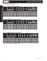
Page 1: ...nit Placement 4 Rigging Mounting Inspection General Safety Information Control Factory Default Settings 5 Standard Installation Procedure 6 Outdoor Unit Installation Instructions 7 2 Freezers Service...

Page 2: ...ox Temp lbs kg oz BTUH PTT047M6B 5 120 208 230 1 60 7 0 15 5 9 350 A 192 87 27 6 700 PTT063M6B 6 860 208 230 1 60 11 5 15 9 5 550 A 207 94 29 8 700 PTT072M6B 7 500 208 230 1 60 9 3 15 7 8 500 A 211 95...

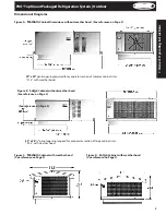
Page 3: ...ood See reference on Page 2 Dimensional Diagrams Figure B Large Cabinet without weather hood See reference on Page 2 25 x 381 2 panel opening required for evaporator section of large cabinet sizes 23...

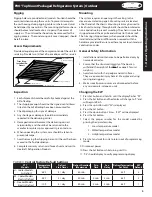
Page 4: ...ck any panel cam locks to install top mounted equipment The size and shape of the storage will generally determine the type and number of units to be used and their location Top View One System Evapor...

Page 5: ...prior approval is given to do so 6 When unpacking the system care should be taken to prevent damage 7 Avoid removing the shipping base until the unit has been moved to the final destination 8 Complete...

Page 6: ...nstallation to prevent bunching or folding which could affect the gasket to curb sealing or trap rainwater adjacent to the curb 4 Remove the weather hood from the system The compressor compartment cov...

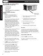
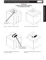
Page 7: ...re 2 Roof membrane placed over curb Figure 3 PTT unit placed on roof of walk in color see rigging instructions Figure 4 Weather hood installed after electrical service connection PTT Models Example Ou...

Page 8: ...functioning properly 8 Clean the evaporator coil surface 9 Clean the drain pan and check the drain pan and drain line for proper drainage Refrigeration Sequence of Operation 1 Power is provided to the...

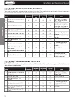
Page 9: ...Off Off Off If unit shows OFF depress the button and hold for three seconds On Automatic Defrost on start up Off Off Off On If coil temperature is below 65 F If it is above defrost is not initiated D...

Page 10: ...Compressor starts and evaporator fans delay for 2 minutes to freeze coil TABLE 6 Model PTT Medium Temperature Models EZY SETTING 2 SET POINT IS 34 F These models are intended for cooler applications a...

Page 11: ...lling template If necessary unscrew the two screws Do not unscrew excessively the screws must not be detached from the front panel phase 1 Insert the instrument in the opening in the panel and hold it...

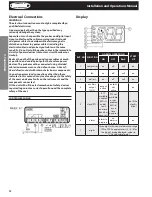
Page 12: ...section of each wire 0 5 mm2 Avoid direct contact with internal electronic components Connection errors and connections other than those indicated in this manual may involve danger to the safety of th...

Page 13: ...al timer relating to parameter dI is updated If dI expires in OFF status a defrost is performed when restarting auxiliary relay management only in the following configurations H1 1 2 E0 alarm only H1...

Page 14: ...multifunction input analogue or digital Parameter 4 selects the probe shown on the display all the other display and control modes remain unchanged IMPORTANT the easy compact models can display up to...

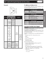
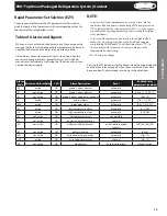
Page 15: ...arameters with corresponding values for the control of the refrigeration system Table of Alarms and Signals When an alarm is activiated the display shows the corresponding message that flashes alterna...

Page 16: ...Ad and A0 The alarm is automatically reset when the temperature returns within the set limits see parameter AL HI flashing High temperature alarm The probe has measured a temperature higher than the s...

Page 17: ...until displaying 22 password to access the parameters press the SET button to confirm the password use the UP and DOWN buttons to scroll the parameters The LED corresponding to the category of paramet...

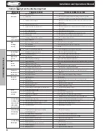
Page 18: ...mperature is too high parameters dt and d defrost probe the manual defrost is not activated and the defrost LED flashes compressor protection times set parameter d9 select d9 1 the high temperature al...

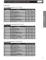
Page 19: ...0 r2 Maximum set point value 0 150 50 c2 Minimum compressor off time 0 100 4 do Type of Defrost 0 4 0 dI Interval between defrost 0 199 6 dt End defrost temperature set point 50 127 65 dP Maximum def...

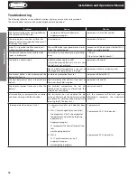
Page 20: ...for proper superheat 4 Condensing temperature too low 4 Check ambient temperature 50 F to 100 F Compressor 1 Operating beyond design conditions 1 Add equipment so that conditions are within allowable...

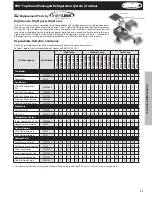
Page 21: ...230V Defrost Heaters 4313F 3 3 3 3 3 3 3 3 Outdoor Parts Fan Pressure Control 28917301 1 1 1 1 1 1 1 1 1 1 1 1 1 1 1 1 1 1 1 1 1 Fan Temperature Control 5521R 1 1 1 1 1 1 1 1 1 1 1 1 Drain Line Heate...

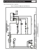
Page 22: ...PRIMARY SINGLE PHASE PROTECTION PROVIDED PRIMARY SINGLE PHASE PROTECTION PROVIDED CCH CRANKCASE HEATER PFC PRESSURE FAN CYCLE SWITCH DLT DRAIN LINE THERMOSTAT DLH DRAIN LINE HEATER TFC TEMPERATURE FA...

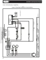
Page 23: ...ACITOR HPS HIGH PRESSURE SWITCH PRIMARY SINGLE PHASE PROTECTION PROVIDED PRIMARY SINGLE PHASE PROTECTION PROVIDED CCH CRANKCASE HEATER PFC PRESSURE FAN CYCLE SWITCH DLT DRAIN LINE THERMOSTAT DLH DRAIN...

Page 24: ...URE SWITCH PRIMARY SINGLE PHASE PROTECTION PROVIDED PRIMARY SINGLE PHASE PROTECTION PROVIDED CCH CRANKCASE HEATER PFC PRESSURE FAN CYCLE SWITCH DLT DRAIN LINE THERMOSTAT DLH DRAIN LINE HEATER TFC TEMP...

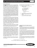
Page 25: ...Heatcraft Refrigeration Products LLC makes no warranty expressed or implied of fitness for any particular purpose or of any other nature whatsoever with respect to products manufactured or sold by Hea...

Page 26: ...is a continuing effort we reserve the right to make changes in specifications without notice Heatcraft Refrigeration Products LLC 2175 West Park Place Blvd Stone Mountain GA 30087 P 800 321 1881 www h...

Reviews: