Page 6
Page 7
E. Lowering The Liner
Carefully lower the first length of conduit into the chimney, until the top is 6 to 12
inches above the chimney top. Secure the lowering rope or have a helper hold it fast.
Attach the next length of conduit (see Figure 5) and again lower the liner. Continue
lowering the liner and attaching lengths until the Tee, Elbow, or bottom section
approaches the opening near the bottom of the chimney.
Using a combination of 4 ft., 3 ft., 2 ft., 18 inch, 1 ft., or 6 inch sections, the conduit
should end at least 3 inches but no more than 14 inches below the top of the chimney.
This space is needed because the conduit expands as it is heated, and will be bridged
by the slip connector part of the termination assembly.
F. Attach Tee Take-Off or Elbow
When a tee is attached to the bottom of the liner, extend the retractable bands on the
tee take-off to the maximum by turning the screw counterclockwise. Do not screw the
end of the band completely out. Position the take-off for the tee in the opening in the
chimney. Lower the base assembly through the band until the hole in the tee is even
with the take-off. With a long-handled flat head screwdriver, turn the screw clockwise
until the take-off is pulled tightly against the tee.
Make sure the take-off is centered
over the hole
, with the projecting lip around the tee hole
inside
the take-off at all
points. Do not overtighen the screw, or distortion of the tee body will result. Verify
by looking in through the take-off that the sides have not been squeezed inward.
When an elbow is to be attached to the bottom of the liner, hold it in the chimney
opening and guide the bottom of the liner into it. Secure it to the liner with the locking
ring and locking tabs per Figure 5.
G. Attach The Support System to the Tee or Elbow
Bend the tabs on the support clamp out about 1/2 to 3/4 inch away from the side of the
tee or elbow. Raise or lower the liner until the tabs engage the edges of the support
bracket or legs. Let the liner rest on the support system and remove the lowering rope.
H. Install The Termination Assembly
Trim the cover plate so that the hole is centered over the flue space. If a clay tile liner
projects from the top of the chimney, trim the cover plate 2 to 4 inches larger than the
outer dimensions of the tile. Cut a rectangular notch out of each corner and fold each
side of the plate down 90 degrees, so that the top surface is slightly larger than the tile.
Run a bead of silicone caulk on top of the tile and press the plate down into it. If there
is no projecting tile, run a bead of caulk around the chimney top and press the cover
plate flat on top of the chimney. Slip the storm collar, with the rounded surface facing
up, onto the slip section up to the expanded end. Reaching in through the slip section,
Make sure that the sections are tightly joined and form a straight, continuous flue gas
conduit. To eliminate snagging of the locking tabs as the liner is lowered down the
chimney, you may wish to tape the ends flat against the conduit with foil tape.
D. Attach Lowering Rope
The lowering rope will allow the liner to be safely and smoothly fed down the
chimney, and held in position while additional lengths are attached. Attach the rope
to the tee, elbow or lowest section of conduit by looping it around the outside of the
section and securing it to the sides of the conduit with duct tape. Locate the tape so
that it can be reached for easy removal from the bottom of the chimney. Never feed
the rope up the inside of the conduit - it will be impossible to attach additional sections!
C. Preassemble Lengths of Conduit
Note: All parts needed for secure joining of conduit sections are attached to
each section.
Never drill through the conduit wall or attempt to join sections using
screws or pop rivets
.
Several sections of Saf-T Vent conduit may be preassembled to manageable lengths
on the ground, to minimize trips up and down the ladder. Generally, lengths of 8 to
10 feet can be safely carried up the ladder and manipulated on the roof. Be sure to
check for overhead power lines and other obstacles, and provide safe and stable
footing, before working with long lengths of conduit.
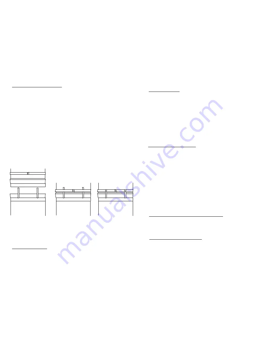
To join sections of conduit, fit the smaller, male end into the flared female end (with
the projecting locking tabs) of the section below, making sure that the locking tabs stay
on the outside (Figure 5-A). Push the loose locking ring upward on the conduit using
the fingers of both hands, press the ends of the locking tabs against the conduit. Let
the locking ring fall over the tabs (Figure 5-B). Push the locking ring downward as
far as it will go. Bend the locking tabs tightly down over the locking ring and tap the
ends against the conduit with a hammer and block of wood (Figure 5-C).
A
B
C
Figure 5


