background image

RMLD-CS 

Operator’s 

Manual


Doc No. 105408 Rev C, RMLD-CS Operator Manual 


© 2021 Heath Consultants Incorporated. All rights 

reserved.


17 


Button Controls  

 
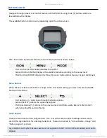
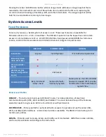
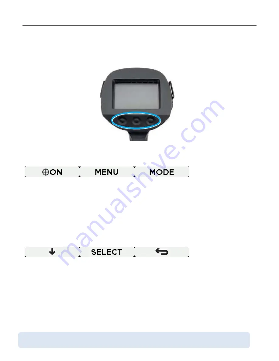
Navigate through screens and control features of the RMLD-CS using three (3) buttons which are 
located below the display.  
 
The available button functions vary depending upon the active screen.  


After instrument is powered ON, the control buttons will be as shown below:


-


First function (

ON) enables/disables the spotter


-


Second function (MENU) displays the available features according to the access level


-


Third function (MODE) displays the three (3) screen mode options (Survey, Graph, and Image)


Menu Buttons 


When Menu is selected, the buttons change to the ones below letting you view and select available 
features in the Menu. 


-


First button 

(↓)

, scrolls down through the Menu options


-


Second (SELECT), selects the option highlighted


-


Third, back arrow (

) returns to the previous level 

and it also works like an “enter/return” 

when entering PIN and User Name.


Other Buttons 


There are two more button configurations.  One to use the camera under the Image screen and a 
second the Login Buttons for entering credentials.  These are covered i

n, “Screen Mode


Image” and 

“Before Login

-

in” sections.


Login Buttons and System Access Levels are not applicable to FW 1.40-2.33-8 (and earlier) and can be 
skipped.  

Summary of Contents for HPN105354

Page 1: ......

Page 2: ...BATTERY PACK CHARGER 13 CHARGING PROCEDURE 14 OPERATING THE RMLD CS 16 TURNING INSTRUMENT ON OFF 16 BUTTON CONTROLS 17 SCREEN MODE SURVEY 18 SCREEN MODE GRAPH 18 SYSTEM ACCESS LEVELS 20 TIERED PERMISSIONS 20 BEFORE LOGIN 21 ADMIN PROFILE 22 FIRST METHOD 22 SECOND METHOD 27 WORKING WITH THE MENU ITEMS 29 AVAILABLE MENU FEATURES FOR FIRMWARE 1 40 2 33 8 OR EARLIER 29 AVAILABLE FEATURES OPERATOR S AC...

Page 3: ...OUND 47 USER PROFILES 47 ABOUT SCREEN 51 ADMIN SPECIFIC COMMANDS VIA USB COMMAND MODE 52 3RD PARTY APPLICATION SUPPORT 53 HOW DOES THE RMLD CS MEASURE GAS 54 SURVEYING WITH THE RMLD CS 56 LONG RANGE SCANNING 58 DEALING WITH FALSE DETECTIONS 59 SCANNING THROUGH WINDOWS 59 COMMON VENTING LOCATIONS 60 TROUBLESHOOTING 61 MAINTENANCE 63 NOTES 64 WARRANTY AND REPAIR 65 RETURN PROCEDURE 66 CONTACT INFORM...

Page 4: ...RMLD CS Operator s Manual Doc No 105408 Rev C RMLD CS Operator Manual 2021 Heath Consultants Incorporated All rights 3 ...

Page 5: ...ual in whole or in part is prohibited without the express written consent of Heath Consultants Incorporated Heath Consultants Incorporated operates under a continual product improvement program and reserves the right to make improvements and or changes without prior notification This manual supersedes all previous manuals for this instrument Doc No 105408 Rev C RMLD CS Operator Manual Copyright 20...

Page 6: ... which the instrument then detects Based on the local meteorological conditions a given amount of gas escaping from the ground will produce a plume that varies in size and uniformity of concentration levels The plume by nature is variable and dependent on the soil type moisture temperature wind venting and leak rate The RMLD CSoperates under avariety offield conditions includinga wide temperature ...

Page 7: ...NGER To reduce the risk of ignition of a flammable or explosive atmosphere batteries must be removed inserted and recharged only in a location known to be non hazardous Read and understand this manual fully before use Follow the manual instructions and testing methods The visible green Spotter laser is a Class 2 II laser product Do not stare into beam or view directly with optical instruments Avoi...

Page 8: ...s product according to local regulations Measurement IR Laser Radiation Class I Visible Green Laser Radiation Class 2 II Do not stare into beam Avoid direct eye exposure NOTE The manual captures information applicable to both firmware releases 1 40 2 33 8 and 1 54 2 38 10 The new firmware release 1 54 2 38 10 added security level features and new menu options not available on earlier versions Thes...

Page 9: ...cal radiation with wavelengths longer than those of the visible spectrum Laser Calibration Drift A normal characteristic of tunable diode lasers is that the wavelength calibration can drift slowly over time The RMLD CS has a built in Self Test Calibration feature to automatically maintain proper calibration PPM M Parts Per Million Meter The product of the methane concentration times the thickness ...

Page 10: ...able Alarm Level from 1 to 999 PPM M Real Time RT Continuous audio beep rate relative to concentration from 10 1000 PPM M System Fault Warning Audible alarm and visual indication on the display Self Test Built in Self Test function verifies operation and adjusts laser wavelength for maximum sensitivity Cal gas cell integrated within carrying case Compliance EMC EN61000 6 2 EN6100 6 4 Radio Equipme...

Page 11: ...cle GNSS Compatible with GPS GLONASS Beidou Galileo Green Spotter Class 2 II 5mW 532nm Spot size is 7mm at 15M Carry Case 21 x 17 5 x 9 5 Battery Pack Removable rechargeable Li Ion pack 10 8 Vdc at 2 6Ah Battery Run Time 8 hours at 32 F approx Battery Charger External 110 240 Vac 50 60 Hz Universal Dual Bay Charge Time 2 3 hours full charge approx LED Charging Indicator Integrated into Dual Batter...

Page 12: ...arger Battery Pack USB Cable Instrument HPN105354 This is the primary component of the RMLD CS In addition to the gas detection capability it contains the user interface data logging interface battery power connector Carrying Case HPN 105355 The carrying case provides protection for the instrument during storage and or transportation It also has a built in cal cell HPN 106024 for calibration The i...

Page 13: ... when fully charged The battery must be recharged between uses to assure no interruption in use Battery Charger HPN 105358 The battery charger is provided to recharge the instrument s battery after use It has 2 slots for dual battery charging The charger is universal 100 240 VAC 50 60 Hz with charger indicator on the front of the housing While charging the LED light will blink green Once a full ch...

Page 14: ...es a remaining battery pack capacity in percent indicator in the top right of the screen The battery pack capacity indicator will turn red when the capacity gets low around 10 and the instrument will prompt the operator for acknowledgement on the display Dual Bay Battery Pack Charger The dual bay battery pack charger supplied with the instrument can charge two battery packs simultaneously An integ...

Page 15: ...al circuits CAUTION To prevent damage to the battery pack or electrical circuits always plug the charger into a surge protected outlet NOTE The prolonged storage of the battery pack inside or outside the instrument can lead to battery chemistry being irreversibly damaged leading to permanent failure of the battery pack When storing the instrument or the battery pack for more than a month charge th...

Page 16: ...ger station displays charging legend a Flashing Green Battery pack charging b Solid Green Battery pack fully charged c No light Battery pack not present or not connected properly d Red Fault replace battery pack i Position battery pack into the other bay if still red try another battery pack ii If the light is still red send to repair or replace 5 Once the battery pack is fully charged power up th...

Page 17: ...ation like the firmware version time and day When done the display will show a Self Diagnostics Ok FW 1 54 2 38 10 or later The first thing the instrument then checks for is a valid passing Self Test file for the day If not found a pop up window appears informing the operator to conduct a Self Test The Self Test prompt must be acknowledged NOTE Boot up Self Diagnostics is not the same as Self Test...

Page 18: ...MODE displays the three 3 screen mode options Survey Graph and Image Menu Buttons When Menu is selected the buttons change to the ones below letting you view and select available features in the Menu First button scrolls down through the Menu options Second SELECT selects the option highlighted Third back arrow returns to the previous level and it also works like an enter return when entering PIN ...

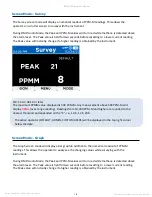
Page 19: ... value displayed is 50K PPM M Any measurement above 50K PPM M will display ORNG over range reading Readings from 10 000 PPM M and higher are rounded to the nearest thousand and appended with a K i e 10 K 12 K 20K The active operator DEFAULT ADMIN CUSTOM USERS will be displayed in the top right corner below the date Screen Mode Graph The Graph screen mode will display a bar graph in addition to the...

Page 20: ...active operator DEFAULT ADMIN CUSTOM USERS will be displayed in the top right corner above PEAK Screen Mode Image The IMAGE mode allows the operator to view a live image of where the RMLD CS is pointed as well as current and peak PPM M readings This feature is especially useful in bright sunlight when the green spotter laser may be hard to see NOTE The center reticle is a general representation of...

Page 21: ...t configuration permissions DEFAULT CUSTOM USER ADMIN Intended for Anyone Field Operator IT or Authorized personnel Streaming Access USB Wi Fi BLE x File Access USB Wi Fi x Web Access File Server Configuration Portal x File Server Command Options Help Command Access Level Same as Default Telemetry System Same as User Set Wi Fi SSID Password Update Wi Fi Display Fault Record Clear Fault Record Syst...

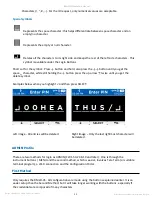
Page 22: ... Wi Fi SSID Service Set Identifier available for both AP and Station Mode They will typically differ Wi Fi Pass password for both AP and Station Mode They will typically differ Login Buttons Usage When entering credentials using the buttons the process can be easier using a set of secondary buttons for navigation This set of secondary buttons help with features that require an operator to enter an...

Page 23: ...space character while still holding the button press the up arrow twice until you get the delete symbol Examples below when you highlight and then press SELECT Left image All entries will be deleted Right Image Only the last rightmost character will be deleted ADMIN Profile There are two methods for login as ADMIN FW 1 54 2 38 10 and later One is through the instrument buttons MENU and the second ...

Page 24: ...rol buttons section for more details The default PIN for ADMIN is 800HEATHUS You will need it for first time login It is highly recommended to change the password When done press the back arrow This will take you back to the USERS screen with the SWITCH TO USER highlighted Make sure to press SELECT or the credentials will not be processed NOTE Firmware 1 40 2 33 8 User profile configurations are c...

Page 25: ...ended to change you ADMIN PIN first and ID The steps below will apply to User profiles as well Changing PIN From the MENU screen select USERS Select appropriate account profile then press EDIT PIN To delete the current PIN use the delete character Check Login Button section Tip To delete the old PIN entirely make sure the delete symbol is at the far left The screen will have an empty space Enter y...

Page 26: ...to accept the changes and return to the previous menu Edit Wi Fi credentials Both the Users and Wi Fi features under the Menu screen allow an ADMIN to change their and other Users Wi Fi credentials NOTE It is required to create credentials before enabling Wi Fi otherwise a prompt will appear asking for SSID or password information Choose from Station or AP mode and their SSID and Password options ...

Page 27: ... New User and SELECT Add New User Automatically the instrument will add a new user under the name NEW It is highly recommended to change the name Editing User s Name Select NEW and scroll down to Edit Name Delete the NEW name using the delete symbol and change the name like changing the PIN When done select the Back Arrow To change the ID PIN and Wi Fi credentials This is the same process as with ...

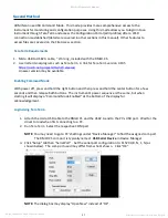
Page 28: ...tssh2 releases A newer version may be available Enabling Command Mode With power off press and hold the right button and then press and hold the center button for a few seconds and then release both buttons The instrument s power sequence is the same but when starting it will display a Command Mode Enabled at the bottom of the display for acknowledgement Login Using Tera Term 1 Attach the micro US...

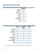
Page 29: ...s command starts by using the small letter o and not the number 0 The return should be Value 0 2 Now you are logged in as ADMIN and you can exit the Tera Term program and disconnect the USB cable from the instrument On the instrument screen modes Survey Graph it should display ADMIN in the upper right NOTE Once you are logged in as an ADMIN covered in this section go to the Wi Fi section under the...

Page 30: ...ator s Access Level Menu For Firmware 1 54 2 38 10 Or Later For the User Default access level the Timezone Offset feature is under the Users feature DEFAULT Self Test Audio Mode Alarm Levels Spotter Control USB Bluetooth Wi Fi Data Logging Time Zone Offset Users About DEFAULT CUSTOM USER ADMIN Self Test Audio Mode Alarm Level Spotter Control USB x x Bluetooth x Wi Fi x Data Logging Timezone Offset...

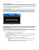
Page 31: ...factory calibration required unless the instrument fails the Self Test repeatedly or presents other problems NOTE The Self Test takes approximately one to three minutes to perform To perform the Self Test the following procedure should be followed 1 Press the MENU button and select the SELF TEST option 2 The screen will display and guide the next steps for the operator to follow within 10 seconds ...

Page 32: ...tic of the RMLD CS The rate of drift is low and Self Test will sweep the laser s wavelength range to determine the optimum wavelength Survey work conducted with an instrument which has drifted and was not Self Tested regularly may need to be redone If the instrument is still not able to successfully perform a Self Test after three attempts contact HEATH for assistance Audio Indications and Modes A...

Page 33: ...ossible when the PPM M reading is high and there is a low light warning While the low signal warning is sounding the RMLD CS may still be able to detect high gas concentrations The Alarm Level controls the response of the DMD The operator can adjust the Alarm Level Your company s survey procedure may require the use of a specific value or procedure to set it Set the Alarm Level such that the false...

Page 34: ...m the leak with the wind to your back if possible 2 Sweep the laser starting from the up wind side in and around the leak area 3 Listen for the fastest beep frequency 4 Change your angle slightly and re scan the leak zone 5 If the location with the fastest beeping is consistent then the location of the surface leak is at that spot 6 If the beeps are not consistent then keep working the area The ga...

Page 35: ... shut off after two minutes requiring the operatorto press the ON button again for use if needed While using the green spotter laser be careful to not point it towards people s eyes or automobile windshields causing vehicle drivers to be distracted Under no circumstances should the spotter laser be pointed at flying aircraft or used near airports The visible green spotter laser is a Class II 2 las...

Page 36: ...2 minutes When the spotter laser is turned ON the icon will change from white to green ON USB FW 1 54 2 38 10 or later This Menu feature is not available for the DEFAULT and CUSTOM USER profiles However the ADMIN profile has two configurations to choose from Command Mode Select to use the USB port as a communication port Communications settings are 115200 8 1 N This is typically used by ADMIN for ...

Page 37: ...le access is available via USB in File Mode or Mass Storage Device and File Server via Wi Fi File access via Wi Fi is discussed later in this manual FW 1 54 2 38 10 or later ADMIN has access to the Configuration Portal via Wi Fi only RMLD CS Folder and File Structure Root Folder Daily Folders Captures Folder Capture Image bmp Capture Log File txt Datalogs Data Log File txt SELF_TEST Folder SELF_TE...

Page 38: ...on first plug in as the required drivers are installed Please allow time for this initial process to complete USB File Transfer in File Mode To access recorded stored data in File Mode or Mass Storage Device 1 Turn on the instrument 2 Use the provided USB 2 0 A to Micro B cable to connect the instrument to PC a Plug the Micro B end into the port on the instrument while powered on b Plug the USB 2 ...

Page 39: ...battery level and various supporting data for usage Instrument files and datalogs are not accessible using BLE To enable Bluetooth streaming the instrument must be paired with a Bluetooth BLE capable device To pair with a Bluetooth capable device Press MENU and scroll down to BLUETOOTH Select and then select PAIR The Bluetooth connection RMLD CS serial number is now broadcasting for discovery NOTE...

Page 40: ...r later Only ADMIN and CUSTOM USERS have access to Wi Fi ADMIN can also configure the instrument through the Configuration Portal The RMLD CS only supports protected networks with WPA 2 security The SSID and password may be entered manually through options provided in the main Menu To enable the Wi Fi feature scroll to Wi Fi in the menu and select either AP or STATION mode as needed AP mode is mos...

Page 41: ...asting and accepting connections When connected the Wi Fi icon will be displayed in the status bar and will be white in color NOTE For FW 1 40 2 33 8 or earlier will display WiFi Broadcasting IP 10 123 451 From your PC or mobile device check the wireless Network connections available and select the appropriate AP SSID RMLD CS is default The AP default password changeme2 is required for connection ...

Page 42: ...ng the same internal folder structures that are accessible through the USB port To access File Server enter the URL address http 10 123 45 1 FW 1 54 2 38 10 or later Only ADMIN and CUSTOM USERS have access to File Server Files can be downloaded and deleted The browser will display the date stamped folders on the SD card Firmware 1 40 2 33 8 Firmware 1 54 2 38 10 From here an operator may select an...

Page 43: ...on mode credentials are supported For file access the Files button must be clicked The operator must then select a date stamped folder using the drop down box selection For a chosen date any stored files that exist in sub folders can be readily identified by the sub folder buttons color Empty folders are gray while folders with files are shown in white For the image above only Datalogs are saved f...

Page 44: ...will read the existing data from the RMLD CS and populate the System Users form with that data This is helpful to validate recent changes Download Users to File will allow the System Users data to be saved to a PC as a JSON formatted text file It is highly recommended to Download Users to File for archival purposes Load Users From File will allow a previously saved System Users file to populate th...

Page 45: ... be named NEW Each User can have different credentials if chosen This is helpful with Wi Fi networks and Timezone Offset for remote operators To delete a chosen user click on the Delete User button in the Custom Users form for that user Remember to Save Users to RMLD to update the changes Data Logging The RMLD CS data logging feature allows the instrument to store complete telemetry records of the...

Page 46: ...e also contains various system status fields and values that can be used to help evaluate instrument performance or aid in troubleshooting if a fault condition occurs Language For FW 1 54 2 38 10 and later only The RMLD CS supports both the English and German languages English as the default language To change setting go to MENU select LANGUAGE then select the desired language Select the back arro...

Page 47: ...rights 46 Firmware 1 54 2 38 10 to the left and firmware 1 40 2 33 8 on the right FW 1 54 2 38 10 or later For CUSTOM USERS accounts the Timezone Offset can be modified by going to MENU select the Users feature and Edit Timezone Offset like the example below for CUSTOM USER Ben The next screen will be Timezone Offset ...

Page 48: ...n displays color according to the Timezone Offset configured USER Profiles User profiles allows multiple operators to utilize the RMLD CS instrument with customized settings and unique PIN password protection to enable use FW 1 54 2 38 10 or later From the Survey or Graph screen mode select MENU then scroll down to USERS then select the desired User profile name Enter the PIN or password by pressi...

Page 49: ...1 40 2 33 8 Required Credentials The table below describes the credential requirements applicable File Type Max Length Supported Characters User Name 20 Space Uppercase Letters and Numbers ID 4 Numbers PIN 4 Numbers Adding a New User Press the MENU button and scroll down to select USERS from the menu Select NEW USER then select ADD NEW USER ...

Page 50: ...ssing SELECT will accept the change and move to the next place holder Pressing the BACK ARROW button will return to the previous menu and accept the name shown Changing User ID Select the user from the menu and scroll to EDIT ID Press select and use the down arrow button to scroll through the numeric options Pressing SELECT will accept the change and move to the next place holder Pressing the BACK...

Page 51: ... PIN Press select and use the down arrow button to scroll through the numeric options Pressing SELECT will accept the change and move to the next place holder Pressing the BACK ARROW button will accept the change in user PIN and return to the previous menu Deleting a User Press the MENU button and scroll down to select USERS from the menu Select the user to be deleted then select DELETE USER ...

Page 52: ...utton to scroll through the available information Model Name and Serial Number 10 digit number Time Stamp HH MM PM MM DD YY Firmware Version x xx y yy z GPS latitude and longitude or GPS location not locked Battery Percent Remaining Internal SD Card Storage Remaining Error Codes Bluetooth Status off on not connected connected Wi Fi Status Heath Consultants Incorporated Contact Information FW 1 54 ...

Page 53: ... Commands use letters and the arguments may be letters and or numbers Usage is as follows Command Description Entry followed by the Enter key h Help Text h o Privilege level o admin 800HEATHUS default password o username userpassword d Data Stream d 1 Stream on d 0 Stream off b Read Build Code b va Set Alarm level va 0 Read alarm level va 1 20 Set alarm level to 20 va 1 alarmlevel Set to alarmleve...

Page 54: ...rty Application Support The RMLD CS supports 3rd party applications Technical documentation is available upon request from Heath Customer Service that defines and documents the setup requirements There are two such documents available 1 RMLD CS Communications Interface Manual This manual describes the telemetry and its format 2 RMLD CS DFU Firmware Update This document describes how to update the ...

Page 55: ...up to 100 ft away actual distance may vary due to surface condition To detect leaks as the above illustration depicts when the infrared laser beam passes through a gas plume and is reflected back the reflected light is collected and converted to an electrical signal that carries the information needed to deduce the methane concentration The laser light is selective to methane and will not false al...

Page 56: ... why it is much easier to detect leaks from a distance of 10 to 15 feet and beyond NOTE There is always a small amount of methane in the air This natural methane background is also measured by the RMLD CS The PPM M reading will then increase as the scanning distance increases NOTE The nature of a gas plume is highly variable The above illustrations are intended to convey the basic theory Some leak...

Page 57: ...he first thing you will need to learn when surveying with the RMLD CS is to control the aiming of the laser and rate of sweeping Radical or abrupt motion may cause the RMLD CS to give false detections due to rapidly changing distance or background that the laser detects Radical or abrupt motion may cause the IR beam to not thoroughly scan the area Here are a few tips for surveying along the main U...

Page 58: ...p and around the piping Note The spotter laser is about 1 25 to the right of the IR laser beam If in doubt and if the leak is underground bar hole the area Scanning during inclement weather these types of conditions reduce the venting of the gas through the soil and the atmosphere It is crucial to understand how inclement weather can affect a leak survey corrective actions and or postponement opti...

Page 59: ...lts when scanning at distances greater than 50 feet it is important to slow down the scanning rate and take care in pointing the laser When taking aim use the spotter laser or the camera feature to ensure proper scanning of the target area Be aware of the ground elevation Scanning across the top of a knoll or past the edge of a structure can result in beam skips a sudden change in distance which m...

Page 60: ... and re sweep across the area to determine if gas is present Scanning from a long range to a short range will also minimize false detection Strong reflections off certain types of surfaces e g black garbage bags water droplets glass polished surfaces stones license plates reflectors etc may give a false detection Re scan the area from a slightly different angle Scanning Through Windows The RMLD CS...

Page 61: ...Doc No 105408 Rev C RMLD CS Operator Manual RMLD CS Operator s Manual Manual 2021 Heath Consultants Incorporated All rights 60 Common Venting Locations ...

Page 62: ... range and lower than normal for long range Laser calibration has drifted Run Self Test Concentration reading low and will not pass the Self Test Laser calibration has drifted Run Self Test up to three 3 times and then contact Primary Instrument Repair Facility Instrument will not turn on Low Battery Replace or recharge battery pack Continual warning sound or screen notification when scanning Scan...

Page 63: ...eplace battery pack and properly dispose of exhausted battery pack Low Signal or Low Light Background surface is absorbing or reflecting the IR light level Change angle to the target to get a better reflecting background Scanning at the range limit of the instrument Move in closer Saturated Background surface is reflecting the IR light level Change angle to the target to get a better background No...

Page 64: ... or equivalent non abrasive lens tissue As needed to prevent dust or water stain build up Self Test Daily to ensure that the instrument is functioning properly Battery pack recharge Recharge to full capacity after each use Replace battery pack As needed When storing a battery pack for one month or more partially charge 30 50 then store in cool dry location As needed CAUTION Only a qualified RMLD C...

Page 65: ...Doc No 105408 Rev C RMLD CS Operator Manual RMLD CS Operator s Manual Manual 2021 Heath Consultants Incorporated All rights 64 Notes ...

Page 66: ...tion alteration modification or service by anyone other than a Heath warranty repair location Batteries and damage from battery leakage and all expendable items such as filters and tubing are excluded from this warranty Heath s responsibility is expressly limited to repair or replacement of any defective part provided the product is returnedto anauthorized warrantyrepair location shipped prepaid a...

Page 67: ...sted suchas o full shipping and billing addresses o instrument or product name model number and serial numbers o brief description of the problem you areexperiencing o the person email address and phone number to be contacted for additional information and approvals 2 Package Your Return Carefully Use the original shipping carton and cushions if available Include all components Include the repair ...

Page 68: ...s Manual Manual 2021 Heath Consultants Incorporated All rights 67 Contact Information Houston Factory Service Center Manufacturing Division 9030 Monroe Blvd Houston TX 77061 Phone 713 844 1300 Fax 713 844 1309 www heathus com Technical Support Phone 713 844 1300 ...

Page 69: ...Heath Consultants Incorporated operates under a continual product improvement program and reserves the right to make improvements and or changes without prior notification ...

Reviews: