

10
598-1135-08
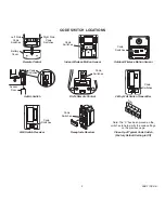
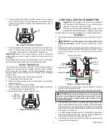
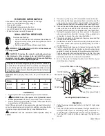
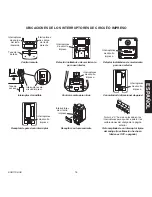
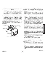
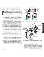
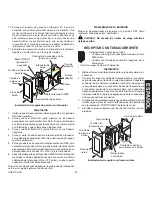
Installing Wall Switch Receiver
Wall Switch Screw
Junction Box
Wall
Switch
ON/OFF Button
DIM Button
Ground Wire (Bare or Green)
Wall
Power Disconnect Switch
Antenna
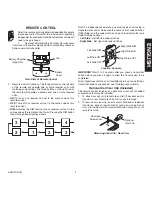
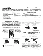
operation
1. Verify the power disconnect switch is in the ON (right side)
position.
2. Push the ON (top) button and release. The light should turn on
full bright.
Note:
If you are controlling a lamp, make sure it is
connected to the switched outlet and the lamp is switched on.
3. Push the OFF (bottom) button and release. The light should
turn off.
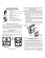
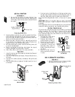
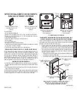
Installation
1. Select light switch to be replaced by wall switch receiver.
2.
waRNING: turn off the power to the light switch circuit
before you proceed.
Do this at your circuit breaker or fuse box.
3. Remove the existing wall plate and switch. Disconnect the two
power wires and the ground wire.
Note:
If there are more than two power wires attached to the switch,
consult an electrician about installation. In addition, some local build-
ing codes may require installation by a qualified electrician.
CautIoN: do not connect neutral (white wire) to
switch.
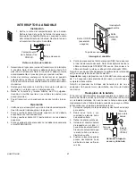
Important Information Regarding 3-way Switch Installations:
In order to use this product where two switches are being used
to control the light, the 3-Way Wall Switch transmitter will also
have to be installed. Refer to the 3-Way Wall Switch Installation
section for details.
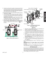
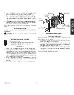
Wall Plate
Screw
Wall Plate
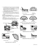
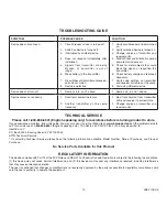
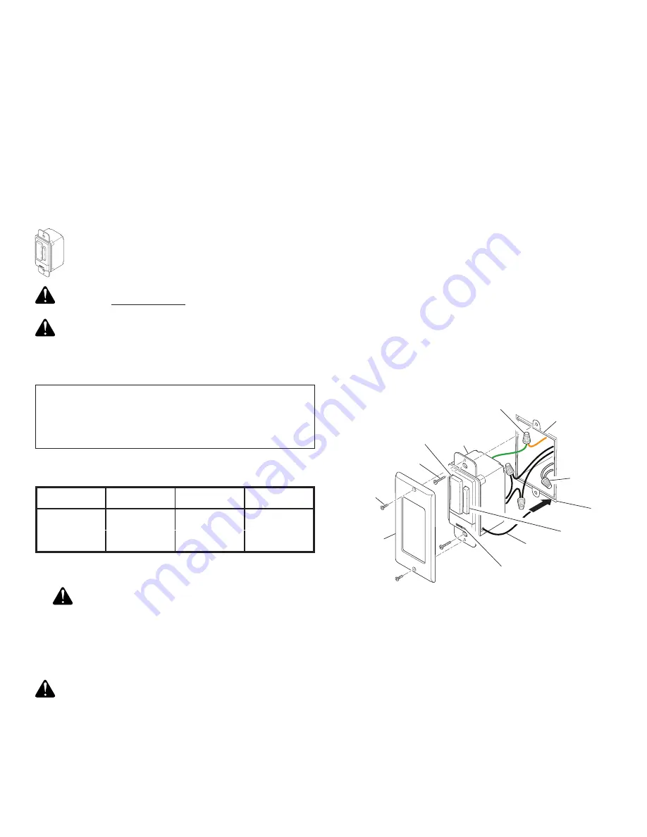
Important:
When ganging these units, they must be derated as
follows:
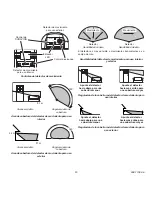
Features and Ratings:
• Up to 500 Watt maximum incandescent load depend-
ing upon switch purchased. See rating label on switch
for exact load rating.
• Not for use with Compact Fluorescent bulbs.
waRNING: FoR uSE oNLY with 120 volt incandescent
or halogen bulbs.
CautIoN: to reduce the risk of overheating and pos-
sible damage to other equipment, do not install to control a
receptacle, a motor-operated appliance, a fluorescent lighting
fixture, or a transformer-supplied appliance.
waLL SwItCH RECEIVER
RECEIVER INFoRMatIoN
All receivers have the following features and ratings:
• Rated for 120VAC/60Hz supply voltage.
• Uses existing wiring.
• Fits standard single gang junction box.
• Up to 100 feet (30 m) typical transmission range.
• When first turned on wait 15 seconds.
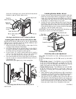
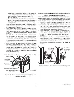
. If necessary, strip away 1/2" of insulation from end of wires.
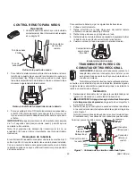
5. Connect one of the black power wires from receiver to one of the
power wires you removed from the old switch. Use one of the
supplied wire connectors to secure the wires (see illustration).
6. Connect the second black power wire from receiver to the other
power wire you removed from the old switch. Use one of the
supplied wire connectors to secure the wires (see illustration).
7. Connect the green ground wire from receiver to the ground
wire removed from old switch. Use one of the supplied wire
connectors to secure the wires (see illustration).
8. Check wire connections to make sure they are secure and that
no bare wires are exposed.
9. Route antenna between the bottom of the junction box and the
wall. Feed antenna into wall cavity while placing wall switch
into junction box.
10. Position the wall switch receiver in the junction box with the DIM
button located to the right. Use the two wall switch screws (long)
supplied to mount the receiver to the wall box (see illustration).
Push excess wiring into wall box while you do this. You may
need to bend the wires to fit inside the box. Mount wall plate on
wall switch receiver with screws (short) provided.
11. Turn on the power to the light switch circuit. Do this at your
circuit breaker or fuse box.
Gang
1
2
3
300 W
300 W
300 W
300 W
500 W
500 W
75 W
50 W
White
(Neutral)


