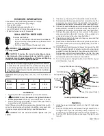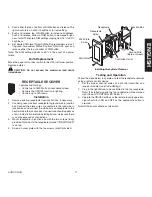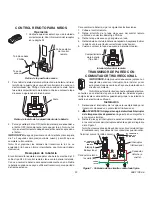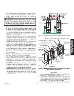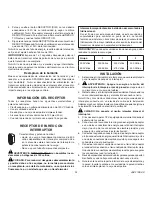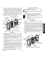
11
598-1135-08
ENGLISH
RECEPtaCLE RECEIVER
Features and Ratings:
• Control up to 1800 Watts of incandescent load.
• Controls the ON/OFF function in lighting.
• Controls up to 15A loads.
Installation
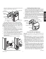
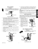
1. Remove existing receptacle from junction box, if necessary.
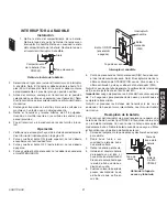
2. Connect green wire from receptacle to ground wire in junction
box. Connect the black wire on receptacle to the load wire in
junction box and connect the white wire on receptacle to the
neutral wire in the junction box. Connections should appear as
shown in illustration. Before installing fixture, make sure there
is no wire exposed at connections.
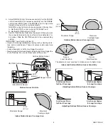
3. Mount receptacle in junction box with the two screws (long)
provided.
Note:
Verify the receptacle marked “CONTROLLED”
is on top.
. Screw on cover plate with the two screws (short) provided.
CON
TRO
LLE
D
Installing Receptacle Receiver
CON
TRO
LLE
D
Receptacle
Screw
Ground Wire
(Bare or Green)
Junction Box
Receptacle
testing and operation
Follow the steps below to operate and test the receptacle receiver
using a remote control device:
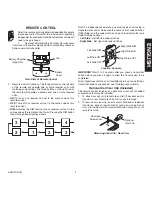
1. Set the proper channel codes on both the transmitter and
receiver modules (see
Code Settings
).
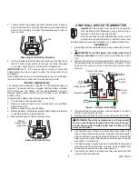
2. Plug in the light fixture to be controlled in the top receptacle.
Note:
If installed properly, the top receptacle will be marked
with the word “CONTROLLED” below it.
3. Operate the ON/OFF buttons on the remote to verify operation.
Light should turn ON and OFF as the appropriate button is
pressed.
Note:
DIM is not available on this switch.
Controlled Outlet
Wall Plate
Screw
Wall Plate
. Push either the top or bottom of DIM button and release. The
light should turn on at 50% brightness (or last setting).
5. Push and release top of DIM button to increase brightness.
Push and release bottom of DIM button to decrease bright-
ness.
Note:
There are 5 DIM settings ranging from 15% to 90%
brightness.
6. Set desired DIM level.
Note:
DIM setting remembers last set-
ting used. To recall last DIM setting from ON or OFF, push and
release either the top or bottom of DIM button.
Note:
The DIM setting defaults to 50% in the event of a power
failure.
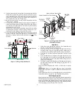
Bulb Replacement
Move the power disconnect switch to the OFF (left side) position.
Replace bulb(s).
CautIoN: do not exceed the maximum load limits
listed above.


