

5
598-1135-08
ENGLISH
(
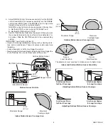
Note:
You should hear a snap). Aim sensor toward area where
detection is desired. Tighten clamp screw.
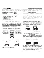
ON
Da
y /
Night
Night
Only
5 1
Te
st
Max
Min
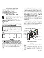
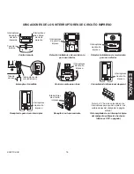
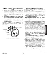
Attaching Indoor Motion Sensor to Mounting Bracket
Mounting
Bracket
Clamp
Screw
Nut
Sensor
Mounting Screw
Swivel Ball Mount
Battery Compartment
Cover
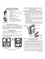
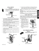
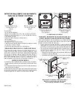
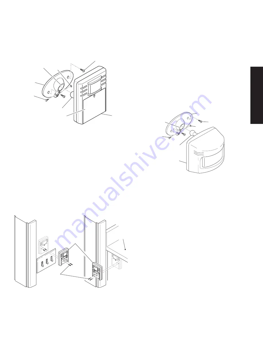
Installing Indoor Motion Sensor directly to wall
Note:
Mount the indoor motion sensor so that it is approximately
between waist and shoulder level above the floor (
Example:
Level
with light switch, under counter top, etc.).
1. Determine the best mounting position of the sensor for the
coverage desired. Remove the batteries.
2. Place indoor motion sensor against surface to be mounted on.
Using two of the holes on the rear of the battery compartment,
mark hole locations with pencil or center punch.
3. Using a 2.5 mm (0.1") drill bit, drill two pilot holes for mounting
screws. If not mounting directly to wood or wood stud, drill 5
mm (0.2") pilot holes and use the included wall anchors.
. Attach indoor motion sensor to a sturdy object (
i.e.
wall, cabinet,
post, etc.) using two screws provided. Make sure unit has an
unobstructed view.
IMPORTANT:
Hand tighten only - do not overtighten.
ON
Da
y /
Nig
ht
Nig
ht
On
ly
5 1
Te
st
Ma
x
Min
ON
Da
y /
Nig
ht
Nig
ht
O
nly
5 1
Te
st
Ma
x
Min
ON
Da
y /
Nig
ht
Nig
ht
On
ly
5 1
Te
st
Ma
x
Min
ON
Da
y /
Nig
ht
Nig
ht
O
nly
5 1
Te
st
Ma
x
Min
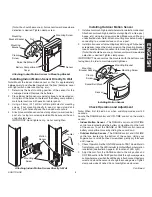
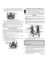
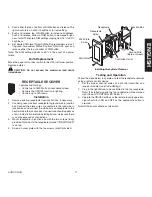
Attaching Indoor Motion Sensor Directly to Wall
Mounting
Screw
Motion
Sensor
Counter
Top
Mounting
Bracket Socket
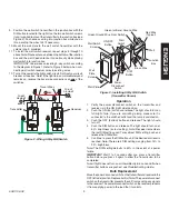
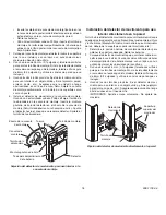
Continued
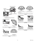
Installing Motion Sensor
Mounting Bracket
Clamp
Screw
Nut
Sensor
Mounting Screw
Swivel Ball Mount
Mounting
Bracket Socket
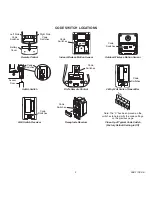
Installing outdoor Motion Sensor
1. Install sensor mounting bracket where motion detection is desired.
Attach sensor mounting bracket to a sturdy object (
i.e.
tree, post,
house, etc.) using two screws provided. Make sure unit has an
unobstructed view.
Note:
Attach mounting bracket vertically if
connecting to a curved surface such as a post.
2. Install motion sensor to mounting bracket. Using a Philips-head
screwdriver, loosen the clamp screw on the mounting bracket.
Insert swivel ball mount on sensor into mounting bracket socket
(
Note:
You should hear a snap). Aim sensor toward area where
detection is desired. Tighten clamp screw.
IMPORTANT:
The sensor must be mounted with the bottom cover
facing down in order to maintain water tightness.
Check operation and adjustment
Note:
When first turned on or when switching modes wait 30
seconds.
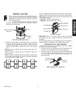
Locate the RANGE control and ON-TIME control on the motion
sensor:
•
Indoor Motion Sensor -
The RANGE control and ON-TIME
control are located inside the battery compartment on the front
of the sensor. To set the RANGE or ON-TIME control, remove
battery compartment cover by sliding the cover down.
•
outdoor Motion Sensor -
The RANGE control and ON-TIME
control are located on the bottom of the sensor. Using your
fingernails or a small, flat-head screwdriver, gently pry the cover
until it opens.
1. Check Operation. Set the ON-TIME control to TEST mode. Walk in
front of sensor unit. The LED indicator light should flash when motion
is detected (see illustration, page 6, for location of LED light).
2. Adjust Sensor. Turn the RANGE control to the mid position and
ON-TIME control to the TEST position. Walk through coverage area
noting where you are when the LED begins to flash. Loosen the clamp
screw and move the sensor to change the coverage area. Tighten
clamp screw when finished. Do not overtighten clamp screw.


