Solar Powered
Motion Sensor Light
Model 7101
FeatureS
• Turns on light when motion is detected.
• Automatically turns light off.
• Photocell keeps the light off during daylight hours.
• Battery Protection Circuitry. Unit will shut down when
battery is low. Unit will automatically resume operation
when battery is recharged to a safe level.
requireMentS
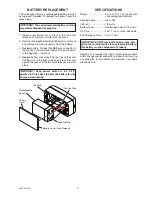
• Do not turn the light on before the battery is fully charged.
Charge the battery by keeping the switch in the OFF
position. Plug the solar panel cable into the bottom of
the battery case. Point the solar panel directly at the
noon sun for 3 sunny days. If not fully charged, the unit
will not work.
• When FULLY charged, the solar light will operate a
maximum of 15 days without sunlight. Actual operating
time will vary depending upon how frequently the light
is triggered.
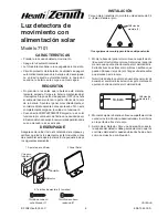
Light
Battery Case
Sensor
3. Mounting Screws (2 sizes)
1. Solar Light Fixture
2. Solar Panel
Tapered Screw (3)
Round Head Screw (2)
unPacking
Be sure to remove all contents from packaging and verify
all items are present before assembling this light fixture.
This package includes the following items:
inStaLLatiOn
For best performance, mount the fixture about 8 feet (2.4
m) above the ground.
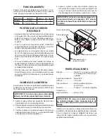
1. Mount solar panel base on a solid surface using three
tapered screws. Adjust the panel to point directly at
the noon sun. Avoid obstructions such as trees or
buildings that may block sun light. Allow for enough
wire to reach the case.
Note: You will want to re-aim the solar panel as the
seasons change to keep it pointed directly at the noon
sun.
Three Mounting Holes for Solar Panel Base
2. Mount the battery case on a solid surface using two
round-head screws and the keyholes on the back of
the case.
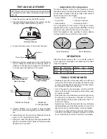
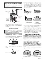
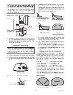
3. Adjust sensor. For proper operation, the sensor head
must be rotated so that the sensor controls face down-
ward as shown below.
5
3
/
4
"
Mounting Holes (3)
Mounting
Holes (2)
4. Plug the solar panel cable into the bottom of the battery
case.
IMPORTANT:
allow the battery to charge
with three days of sunshine before testing.
Controls
Light
Battery Case
Sensor Joint
Clamp
IMPORTANT:
the controls must face downward to
avoid damage from rain.
If controls face upward, move
sensor to the original down position, rotate 180°, then
raise to the position shown below.
Light Joint Clamps
Lens Removal
Tab
Sensor
© 2008 HeathCo LLC
598-1344-00


