36
Heatilator • ICON DV-IDV Series • 4042-575 Rev G • 09/07
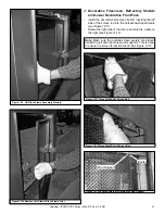
D. Junction Box Installation
If the junction box is being wired from OUTSIDE of the appli-
ance (
preferred method
):
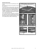
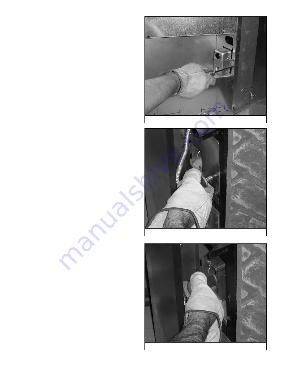
• Remove two screws that attach junction box and bracket
to appliance. See Figure 10.2.
• Feed an appropriate length of romex through plastic romex
connector.
• Make necessary electrical connections.
• Attach outlet and cover plate to junction box.
• Reattach junction box and bracket to appliance with two
screws.
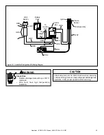
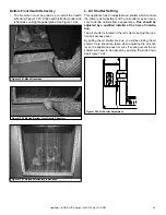
Figure 10.2 Remove Two Screws From Bracket
If the junction box is being wired from the INSIDE of the ap-
pliance:
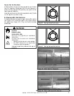
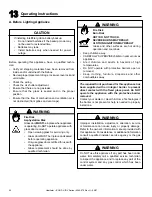
• Remove one screw that attaches access panel to column.
See Figure 10.3.
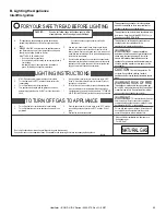
• Remove two screws that attach junction box to junction
box bracket. See Figure 10.4.
• Feed an appropriate length of romex through plastic romex
connector.
• Reattach junction box to junction box bracket with two
screws.
• Make necessary electrical connections.
• Attach outlet and cover plate to junction box.
• Reattach cover plate to column with one screw.
Figure 10.3 Remove Access Panel Screw
Figure 10.4 Remove Two Screws Holding Junction Box


