IMPORTANT
PLEASE READ THIS BEFORE INSTALLATION
SAFETY & WARNINGS
•
This device contains a button lithium battery that shall be
stored and disposed properly.
•
DO NOT expose the device to moisture.
QUICK START
•
Step 1: Turn on your remote control.
•
Step 2: Activate inclusion mode on your Z-Wave controller.
•
Step 3: Activate inclusion mode of your remote control by
pressing and holding down both
I
and
O
buttons together
over 3 seconds.
PRODUCT DESCRIPTION
The remote control is a Z-Wave device that can both control
other Z-Wave devices and activate scenes in Gateways.
Although it is controlling other devices, the device cannot act
as Z-Wave network controller (primary or secondary) and will
always need a Z-Wave network controller to be added into a
Z-Wave network.
The remote control has following functions:
1.
Control of groups of other Z-Wave devices using ON, OFF and
Dim commands.
2.
Activation of scenes in Gateway mode.
The encryption modes that the remote control supports are S0,
S2 Authenticated and S2 Unauthenticated. When the remote
control is being included into a Z-Wave network, you can use
your primary controller/gateway to enable one encryption
mode or disable encryption. (The primary controller/gateway
shall support encryption mode configuration).
INSTALLATION GUIDE
Please read carefully the enclosed user manual before
installation of remote control, in order to ensure an error-free
functioning.
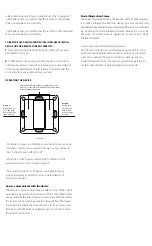
The remote control unit supplied as complete set for flush
mounting in the standard circular European wall boxes with
60mm diameter.
ADDING TO A Z-WAVE NETWORK
Step 1.
Make sure the remote control does not belong to
any Z-Wave network, short press any button, if LED indicator
does not turn on, the remote control does not belong to any
network, then continue step 2, if LED indicator turns on, it
means the remote control has already been added to a network,
please first set the remote control to removing mode (refer to
the part ”Remowing” of this manual), then continue to step 2.
Step 2.
Set primary controller/gateway into adding mode
(Please refer to your primary controllers manual on how to turn
your controller into adding).
Step 3.
Press and hold down both buttons
I
and
O
over 3
seconds, LED indicator turns on, the remote control will be
set to adding mode, and waiting to be added, after 10s LED
indicator blinks 6 times quickly to indicate successful adding.
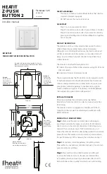
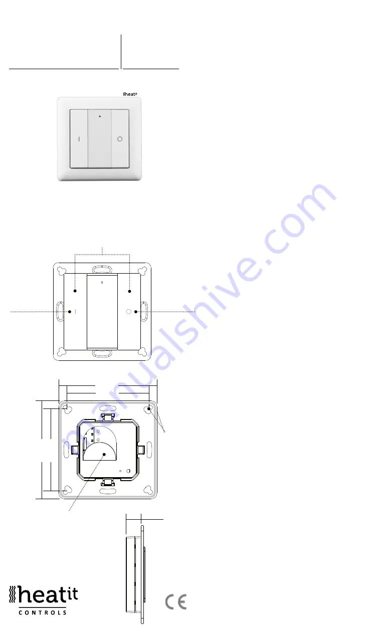
HEATIT
Z-PUSH
BUTTON 2
Firmware 1.25
01.09.2018
Installers manual
Ver 2018-B
55.57 mm
71.20 mm
14,6 m
55
.5
7 m
m
71
.2
0 m
m
m
Battery: CR 2450
Before the first use, please
remove the protective film
Back side
Press and hold down both keys together for 3s to be
added to or removed from Z-Wave network by Z-Wave
master (primary) controller.
Group 2:
Click to turn on,
Press and hold
down to increase
light intensity
Group 2:
Click to turn
off, Press and
hold down to
decrease light
intensity
Front side
The remote
control can be
fixed on the
wall with 3M
glue or screw.
55.57 mm
71.20 mm
14,6 m
55
.5
7 m
m
71
.2
0 m
m
m

