background image

16 


Design and Installation 

   STEP 8     INSTALL GUTTERMELT

® 

SR HEATING ELEMENT 

Install the selected activator by carefully following the specific set of 
instructions that were included in the packaging. 

   STEP 7       INSTALL THE ACTIVATOR 

Warning:  Do not allow the sensor conduit to cross the Gutter-
Melt

®

 SR Heating Element.  Do not allow any part of the activa-

tor to touch the GutterMelt® SR Heating Element. 

Note:  Always roll or uncoil the GutterMelt

®

 SR  to 

unreel the heating element.  Do not pull 
GutterMelt

®

 SR from the spool or coil.  Never 

energize GutterMelt

®

 SR Heating Cable while it is 

rolled or coiled on the spool. 

Using the determined  spacing of GutterMelt

®

 SR Heating Element, and 

the calculated length of GutterMelt

®

 SR Heating Element, begin the 

installation.  Heatizon Systems recommends  a maximum 2 foot 
spacing along the eave edge for roof applications, and two runs of 
GutterMelt

® 

SR for gutter and downspout applications.  Note that the 

minimum distance between the GutterMelt

®

 SR Heating Element runs 

should not be less than 2 inches.    
 
Install the GutterMelt

®

 SR Heating Element so that the starting and 

ending connection points and any activation sensor are in their desired 
locations.  Make certain that the power end of GutterMelt

®

 SR Cable 

returns back to the GutterMelt

®

 SR Termination Box, Junction Box, or 

Heatizon Relay Panel. 
 
Begin laying the GutterMelt

®

 SR Heating Element in and across the 

area to be melted in evenly spaced runs.   
 
Use 

Roof Clips 

purchased from your Heatizon Systems Distributor to 

attach GutterMelt

®

 SR to the roof covering material.   

  
Use 

Foil Tape 

purchased from your Heatizon Systems Distributor to 

attached GutterMelt® SR to the rain gutter. 
 
Use 

Downspout Hangers

 purchased from your Heatizon Systems 

Distributor to install GutterMelt® SR into the downspouts or drains. 

Warning:  Do not damage or subject the 
GutterMelt

®

 SR Heating Element to mechanical 

or shear stress.  Never cut or damage the 
insulator on GutterMelt

®

 SR Heating Element.  

Do not allow GutterMelt® SR to cross or touch 
gas lines or other electrical conductors. 

Note:  Visually check GutterMelt

® 

SR Heating 

Cable for breaks, cuts, nicks, etc.  If damage has 
been done to GutterMelt

®

 SR Heating Cable or 

any of its components, please file a claim with the 
delivery service and call Heatizon Systems, 888-
239-1232. 

MEASURE AND 

RECORD  

RESISTANCE 

  STEP 9  INSTALL GUTTERMELT

® 

 END KIT, POWER CONNECTION KITS  

Commonly used connection kits and accessories are listed in this manual.  See 
www.heatizon.com for additional information. 

After Installing GutterMelt

®

 SR Heating Element take resistance 

measurements. Using a 2500 Vdc Megohmmeter, check the insulation 
resistance of the Heating Element to make certain it is greater than 
20M

. Confirm the Megohmmeter result by measuring the resistance 

with a Digital Multimeter and record the value measured on 

Resistance 

Recording Table 

at the back of this manual.  Resistance measurement 

must be taken several times during the installation process:  
Immediately upon removal from the packaging, after installation of the 
heating element. GutterMelt

®

 SR should also be checked for electrical 

continuity.  

Summary of Contents for Gutter Melt SR

Page 1: ...www heatizon com 2017 Heatizon Systems HEATIZON SYSTEMS RADIANT HEATING AND SNOW MELTING SYSTEMS GutterMelt SR is a registered trademark of Heatizon Systems 07 17...

Page 2: ...2...

Page 3: ...minders 6 GutterMelt SR Cable Layout Design Guidelines 7 GutterMelt Accessories 9 GutterMelt Activation 11 Design and Installation 13 Resistance Recording Page 18 Warranty 19 Note Before proceeding wi...

Page 4: ...ach the cable to standard roof covering material The cable can also be inserted in downspouts using downspout hangers or brackets Heatizon Part HT38411 or HT386412 to support the heating cable GutterM...

Page 5: ...Electrical Code CEC part 1 and local codes and regulations Note Ground fault protection must be used when installing all GutterMelt SR products Refer to the NEC or CEC for specific requirements Note D...

Page 6: ...ed to a suitable earth ground Do not exceed the maximum circuit lengths listed in this Design and Installation Manual Always remember to test the insulation resitance using a 2500 VDC Megohmmeter veri...

Page 7: ...R are attached with a screw or nail GutterMelt cable is installed then a water sealing caulking is applied around the clips screws and nails to prevent leaks Sloped Roof with Gutter and a Valley Exten...

Page 8: ...rMelt in down spout or drain to prevent damage to cable Downspouts A continuous path for melt water can be maintained by running the Gut terMelt inside the downspout to the bottom and extend a small d...

Page 9: ...n GutterMelt is secured to angled bracket no fasteners required Includes UV resistant plastic wire ties Includes two 2 downspout hanger bracket assemblies Prevents heating cable from being damaged at...

Page 10: ...C or 300 feet 5W 120VAC GutterMelt SR Cable Contains GFCI with 30mA test and reset Power ON indicator light Requires NEMA5 20 Amp Outlet Receptacle HT393473 PT 15 Amp 120VAC Plug in Pig Tail Set Used...

Page 11: ...Mounted Sensor One 30A Contact Activates System when moisture is detected and temperature is below set point Leaves system on for up to 6 hours Requires 100 277VAC Switches up to one 30A Loads M326CD...

Page 12: ...ion device Provides two different delay features Powered by 12VDC provides 24VAC for activation device as well as up to 12 circuits of monitoring M332 Gutter Controller Gutter Controller allows Heatiz...

Page 13: ...erMelt SR is designed for snow melt applications and to provide a path for water to exit the roof gutter and downspout drain STEP 1 PLAN THE LAYOUT Note Make certain to plan for the movement of the wa...

Page 14: ...started at 40 F 0 F 20 F 505 475 420 650 560 765 765 9GM1 If started at 40 F 0 F 20 F 320 210 185 425 270 245 455 405 370 460 460 12GM1 If started at 40 F 0 F 20 F 240 155 135 315 210 180 375 310 270...

Page 15: ...tivators require human action as a result they should be placed in a location that is convenient and easily accessible STEP 6 LOCATION SELECTION STEP 3 CONTACT YOUR GUTTERMELT SR SUPPLIER Contact your...

Page 16: ...chased from your Heatizon Systems Distributor to attach GutterMelt SR to the roof covering material Use Foil Tape purchased from your Heatizon Systems Distributor to attached GutterMelt SR to the rain...

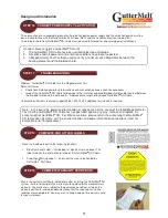
Page 17: ...of 20 MegOhms between the heating element and the braided shield STEP 12 COMPLETE AND ATTACH LABELS STEP 11 TROUBLESHOOTING Problem GutterMelt SR Cable fails the Megohmmeter Test Potential Causes Chec...

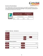
Page 18: ...00 VDC at least twice The measured value should not be less than 20 Megohms Record all test results below Prior to Installation When removed from Package After Installation of GutteMelt SR Heating Ele...

Page 19: ...urchased from Heatizon Systems integrated into or connected to them 4 Any labor costs for removal of alleged defective part s and or reinstallation of replacement part s transportation to and from Hea...

Page 20: ...20 Mail Heatizon Systems 4137 South 500 West Murray UT 84123 USA Phone 801 293 1232 Toll Free 888 239 1232 Fax 801 293 3077 Email info heatizon com Website www heatizon com...

Reviews: