2
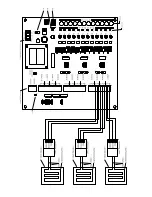
Activation Connection.
Connect the wires from the Activation Device to the plug-in wire
connector identified as J2 and located in the lower right hand portion of the M329 Selector
Box green board. Note: Connect the activation device to pins 1 and 2 (the upper two plug
in wire connectors of J2). Connect all activation devices that require 24 volt power to pins
3 and 4 (the lower two plug in wire connectors of J2). Note: Activation devices requiring
other than 24-volt power must be powered by sources other than the M329 Selector Box.
Control Unit Connection.
Connect the Thermostat connections from each Heatizon
Control Unit to the M329 Selector Box by using the plug in wire connectors labeled J3, J4,
and J5 using #18 Gauge Thermostat wire. Note: Up to a total of twelve (12) Heatizon
Systems CBX, SLC or Radiant 8 Series Control Units may be connected to one M329
Selector Box. Wire each Control Unit to a M329 Selector Box zone by connecting the
following:
Green Wire to BL
Red Wire to R
White Wire to W
To activate the Heatizon Relay Panel (Heatizon Part No. M330) from a Heatizon
Selector Box (Heatizon Part No. M329), connect input terminal numbers 16 (white) and
17 (red) to the Zone 12 red and white terminals on the Heatizon Selector Box. Be sure
to observe polarity red on the M330 to Zone 12 red on the M329 and white on the M330
to white Zone 12 on the M329.
OPERATION
On/Off Switch.
The on/off switch for the M329 Selector Box is labeled S13.
Time Delay.
The M329 Selector Box allows you to determine the amount of time that the
Control Unit(s) will stay on after the activation device has sent a turn off signal. S14 is a
time delay switch that will keep the Control Units on for 0, 1, 2, or 4 hours after the
Activation Device turns off. Set the Time Delay Switch S14 for the desired delay time. Note:
Any time more than one switch is in the on position, the shorter delay will prevail.
Position 1 On, all others Off = no delay
Position 2 On, all others Off = 1 hour delay
Position 3 On, all others Off = 2 hour delay
Position 4 On, all others Off = 4 hour delay
When the D14 LED is blinking the activation device is off and the time delay is running.
Zone Switches.
The Zone Switches marked S1 through S12 allow each Control Unit to be
in “manual,” “automatic,” or “off” mode. Zone Switches that do not have a Control Unit
connected to them must always be set in the “off” position. The Zone Switches that do
have a Control Unit connected to them may be set in the “off”(center), “manual”(right), or
“auto” (left) positions. Switching one of the Zone Switches that has a Control Unit
connected to it to the “manual” position will turn on that Control Unit only, and it will stay on
until the zone switch is moved to the “auto” or “off” position.
Manual Turn on with a Timer.
The Manual Turn On allows one or more zones to be
manually operated for a specific period of time before automatically shutting off. Select the
desired time to operate manually by setting Time Delay Switch S14 to 1 hour, 2 hour, or 4
hour position. Then, select the zones you want to operate in manual mode for that period
Summary of Contents for M329
Page 4: ......


