®
Heat
Link
www.heatlinkgroup.com
14
TWH – Tankless Water Heater Panels
Installation, Operation, and Maintenance
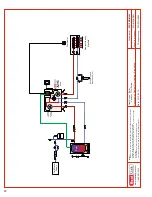
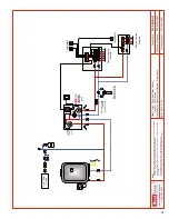
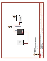
Panel Control Sequence
1. When the power cord
1
from the power module is plugged in, and the Power switch located on the front of the module
is placed in the on position the red LED will be lit, indicating that the panel is powered with 110V.
2. The factory setting for the BYPASS switches
2
are to remain in the OFF position. Only switch the front 3-way switch to
“Heat Source Pump Bypass“ or Radiant Pump Bypass switch to ON if the red and green LED’s on the power module do not
light up during a call for heat. Please refer to the troubleshooting section of the manual for further details.
3. When a thermostat calls for heat, its internal 24V contacts close, the auxiliary terminals close, and both circulators
3
turn on.
4. As the circulators move fl uid through the panel the thermostatic mixing valve adjusts the fl uid temperature based on the
user settings (page 8).
5. When the requirements of the thermostat are met, the internal contacts of the thermostat open, the auxiliary contacts
open, and the circulators stop.
6. Both the primary and secondary circulators are activated once every 24 hours, for 15 minutes, to ensure that potable
water in the piping is not stagnant.
Note:
If the FLWSWTCH optional DHW priority fl ow switch
4
is installed and the DHW fl ow is above the factory setting for
this device, the primary pump stops. When the DHW fl ow drops below the factory setting the primary pump resumes
and the panel returns to normal operation.
1
2
3
4


