13
3.4 ELECTRICAL
WARNING: THIS APPLIANCE MUST BE EARTHED. IT IS SUITABLE FOR
A.C. SUPPLY ONLY. DISCONNECT THE ELECTRICAL SUPPLY BEFORE
REMOVING THE BASE COVER. INSTALLATION MUST BE IN ACCORD-
ANCE WITH THE CURRENT I.E.E. REGULATIONS.
The electrical supply to the property must be checked to ensure it is of
1.
sufficient current rating and voltage.
The immersion heater supply must include a 16A MCB in the circuit.
2.
The circuit must incorporate a double pole isolating switch with a contact
3.
separation of at least 3mm in both poles.
The supply cable should be 2.5mm² 3 core HOFR sheathed and must be
4.
routed via the cable seal and entry provided with the outer sheath of the
cable firmly secured by tightening the screws on the cable clamp.
The wires are colour coded as follows:
5.
Green and Yellow
EARTH
Brown
LIVE
(L)
Blue
NEUTRAL
(N)
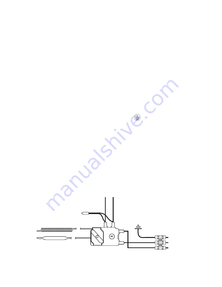
The Multipoint SS water heater has one heating element. The heating
6.
element is controlled by a combined themostat and thermal cut out, refer
to Diagram 04 for wiring details.
DO NOT OPERATE THE IMMERSION HEATER UNTIL THE MULTIPOINT
7.
SS HAS BEEN FILLED WITH WATER.
CUT-OUT SENSOR
THERMOSTAT SENSOR
COMBINED THERMOSTAT
AND CUT OUT
TO ELEMENT
GREEN&YELLOW
BROWN/RED
BLUE/BLACK
ELEMENT EARTH
LIVE (RED)
NEUTRAL (BLACK)
TERMINAL BLOCK
CUT OUT
RESET
A
B
1
2
DIAGRAM 04: WIRING DIAGRAM
NEON POWER INDICATOR


