5
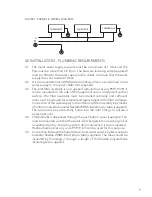
FIGURE 2: SHEMATIC WIRING DIAGRAM
4.0 INSTALLATION - PLUMBING REQUIREMENTS
4.1 The mains water supply pressure must be a minimum of 1.0 bar and the
flow must be more than 2.0 l/min. The pressure reducing valve (supplied)
must be fitted to the water supply to the chiller, to ensure that the water
supply does not exceed 3.0 bar.
4.2 It is recomended that a WRAS listed isolating valve is incorporated in the
water supply to the water chiller (not supplied).
4.3 The inlet filter assembly is not supplied with unit (accessory 95 970 129). It
can be mounted on the side of the SuperChill unit or an adjacent vertical
surface. The filter assembly must be installed vertically and sufficient
room must be allowed for removal and replacement of the filter cartridge.
Connection of the water supply to the chiller and filter assembly is by means
of an 8mm outside diameter flexible WRAS listed plastic tube (supplied).
The tube must be pushed fully home into the inlet fittings to ensure a
water-tight joint.
4.4 Chilled water is dispensed through the push button spout (supplied). This
must be mounted such that the water is discharged into an existing sink or
a suitable drip tray. A drip tray with a drain connection is recommended -
Heatrae Sadia accessory code 95 970 123 can be used for this purpose.
4.5 Connection between the SuperChill unit and outlet spout is by 6mm outside
diameter flexible WRAS listed plastic tube (supplied). The tube should be
insulated by threading it through a length of the flexible polyurethane
insulating tube supplied.
THERMOSTAT
FAN MOTOR
COMPRESSOR
L
N


