6
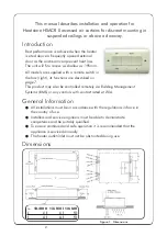
Figure 14: Circuit Diagram 6kW model
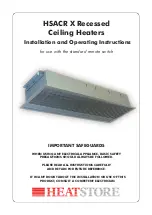
Figure 13: Circuit Diagram 4.5kW model
Electrical Connections
These units are suitable for connection to a 230/240 Volt 50 Hz single
phase supply. The appliance shall be connected to the supply via an
appropriate switched fused double pole isolator having a contact separation
of greater than 3mm. Test for correct operation and refit the cover. For
connection to the mains supply it will be necessary to open the terminal
cover at the side/ back of the unit to connect the supply from the controls
prior to refitting the cover. Wire in accordance to the wiring diagrams.
For safety reasons, a sound earth connection must always be made to the
unit before it is put to use. The unit should be wired in accordance with IEE
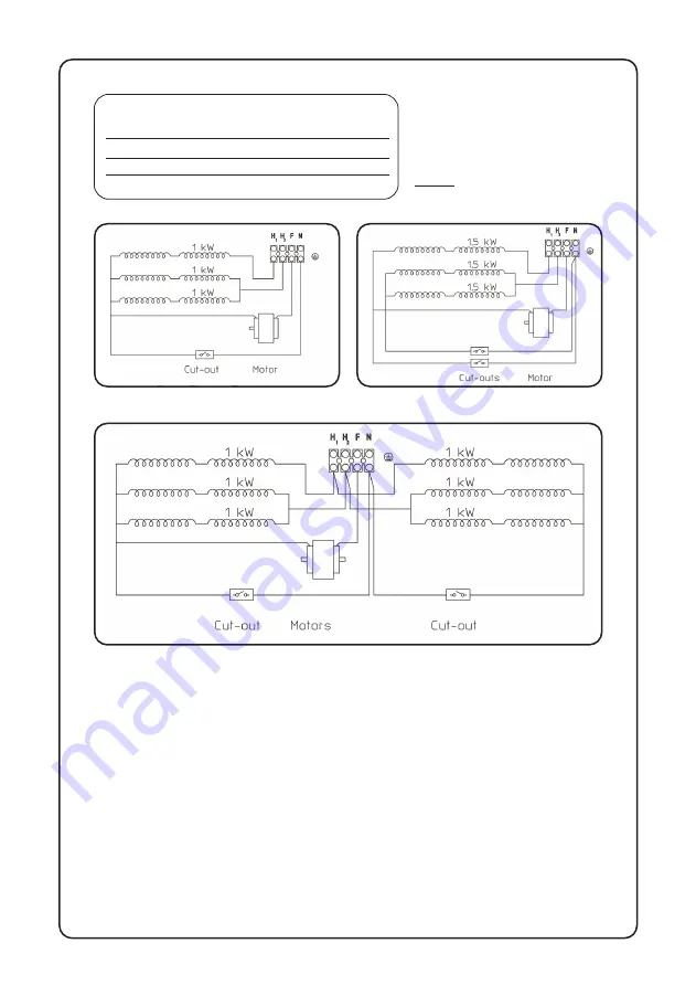
Figure 12: Circuit Diagram 3kW model
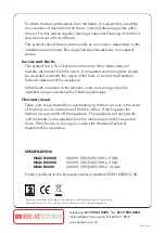
Figure 11: Wiring of heaters
without using remote
switch supplied
WIRED TERMINALS
HSACR3000X
HSACR4500X
HSACR6000
H1+H2+F
3000W
4500W
6000W
H1+F
1000W
1500W
2000W
H2+F
2000W
3000W
4000W
Please note the ‘F’ terminal must always be connected


