background image

MUL

TIPOINT

  3

3

1.0 IMPORTANT INSTALLATION POINTS

1.1

Ensure that the wall or supporting structure is of adequate strength to support the

heater. (Refer to table 1.)

1.2

The Water Regulations require a minimum of 350 mm unobstructed space above

the heater lid to allow the float valve to be replaced. However, a space of 200 mm is

sufficient to replace the HSR Series float valve.

1.3

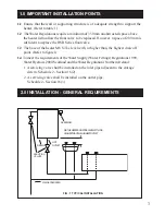
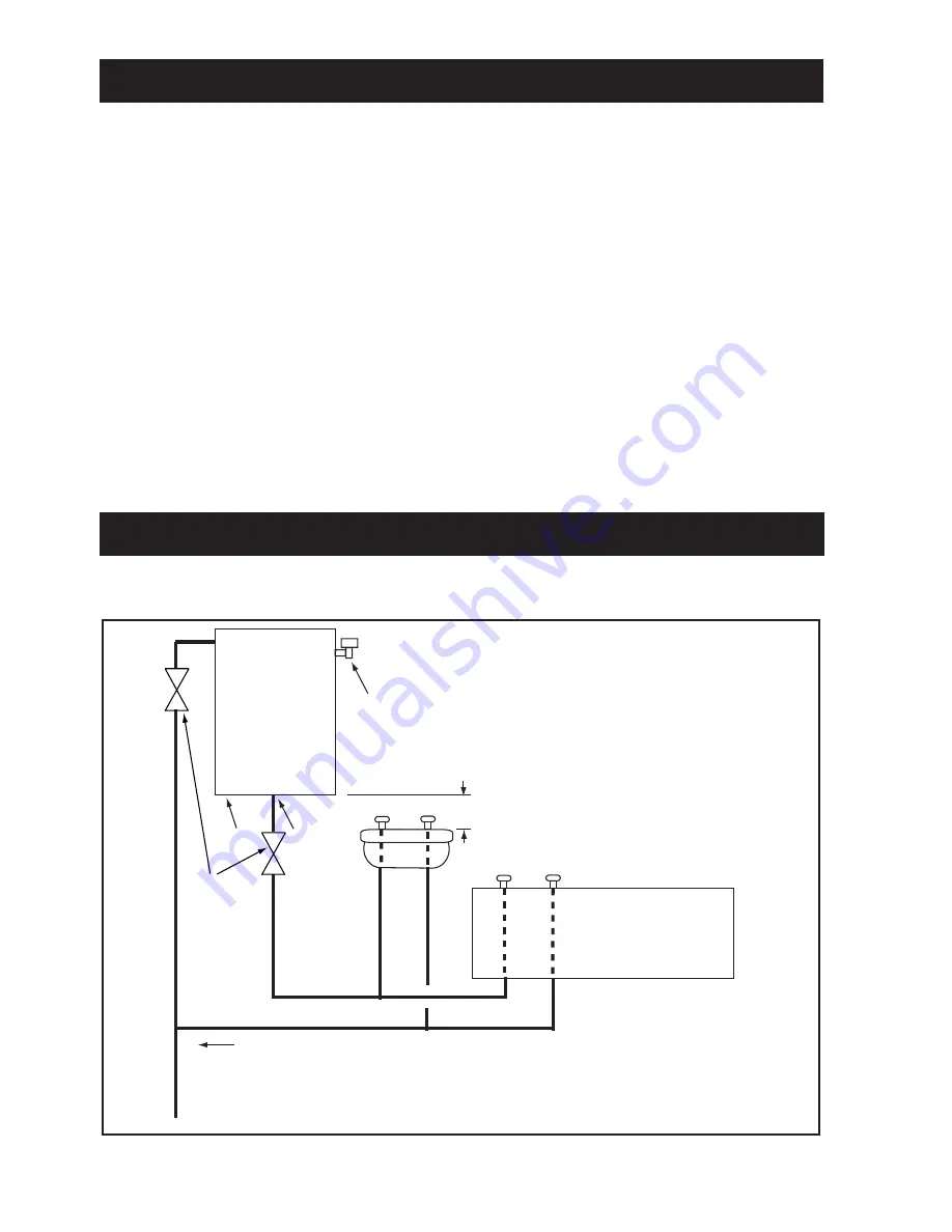
The base of the heater MUST be level with, or higher than, the highest draw off

point. (Refer to figure1)

1.4

 To meet the requirements of the Water Supply (Water Fittings) Regulations 1999,

Water Byelaws 2000 Scotland and the Water Regulations Northern Ireland:
1. A servicing valve shall be installed on the inlet pipe adjacent to the storage

     cistern. Schedule 2 - Section 16(2).
2 . A servicing valve shall be installed on the outlet pipe.

      Schedule 2 - Section 16(3).

2.0 INSTALLATION - GENERAL REQUIREMENTS

DRAIN

HOT
OUTLET

OVERFLOW

MAINS COLD FEED

NB THE HEATER MUST BE LEVEL WITH OR
HIGHER THAN THE HIGHEST OUTLET

FIG : 1 TYPICAL INSTALLATION

SERVICING
 VALVES

Summary of Contents for HSR115

Page 1: ... FloatValve Arm Float Overflow Fitting DipTube Screened Breather WallMountingCollars InstallationandUserInstructions WARNING This water heater must only be installed by qualified persons SY0022400 Revision 6 Please read and understand these instructions before starting work Pleaseleavethisleafletwiththeuserfollowinginstallation HEATSTORE ...

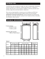
Page 2: ...ON POINTS Following installation and commissioning the operation of the heater should be explained to the customer and these instructions left with them for future reference Electricalrating 2 8 kW 230V 3 0 kW 240V Maximuminletpressure 1 MPa 10 bar 145psi INTRODUCTION TECHNICAL SPECIFICATION Table 1 A B C D E l e d o M s e r t i l s e i t i c a p a C m m s n o i s n e m i D g k s t h g i e W k n a...

Page 3: ... level with or higher than the highest draw off point Refer to figure1 1 4 To meet the requirements of the Water Supply Water Fittings Regulations 1999 Water Byelaws 2000 Scotland and the Water Regulations Northern Ireland 1 A servicing valve shall be installed on the inlet pipe adjacent to the storage cistern Schedule 2 Section 16 2 2 A servicing valve shall be installed on the outlet pipe Schedu...

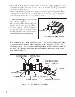
Page 4: ... as shown in figure 2 Locate the heater onto the spacing collars and mark the bottom fixing holes Remove the heater drill the wall and fit the bottom wall fixings 2 4 Fit the float valve complete with float to the cistern tank The float valve is fitted with a white seating which is suitable for inlet pressures from 1bar to 10 bar If the pressure is below 1 bar the seating must be swapped with the ...

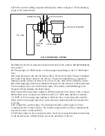
Page 5: ... water supply to the float operated valve using 15mm o d pipe NB the float valve connection is a flat face with a 1 2 BSP male thread Fit a female 1 2 BSP to 15mm copper tap coupling to the float valve A servicing valve must be fitted in the 15mm supply pipe close to the cistern to enable the unit to be isolated for servicing 2 11 Connect the overflow pipe The connection for the overflow pipe is 2...

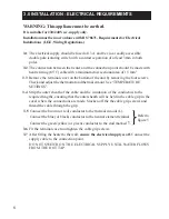
Page 6: ...ff the the cable grip screws and thread the cable through the grip 3 0 INSTALLATION ELECTRICAL REQUIREMENTS WARNING This appliance must be earthed It is suitable for 230 240V a c supply only Installation must be in accordance with BS 78671 Requirements for Electrical Installations I E E Wiring Regulations 3 1 The electrical supply should be fused at 13 A and be via a readily accessible double pole...

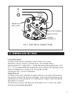
Page 7: ... are not recommended ThermalCut out The heater is fitted with a manually re settable thermal cut out which will interupt the power to the element in the event of overheating In the event of the thermal cut out operating it is re set by pressing the re set button refer to figure 5 after checking the thermostat See section 8 The thermal cut out has a calibrated scale and should be set 15 C above the...

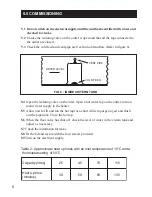
Page 8: ...ur screws provided 5 9 Turn on the electrical supply 5 1 Do not switch on the electrical supply until the unit has been filled with water and checked for leaks 5 2 Ensure the isolating valve on the outlet is open and that all the taps connected to the outlet are closed 5 3 Check the cold feed and vent pipe are free from obstruction Refer to figure 6 5 0 COMMISSIONING WATER LEVEL VENT PIPE COLD FEE...

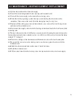
Page 9: ...pply cable from the heating element and undo the four heater plate retaining nuts 6 7 Remove the heater plate If difficulty is experienced in breaking the joint between the heater plate and and water container screw two OBA or M6 screws into into the holes marked F in figure 5 6 8 Check the settings of the thermostat and thermal cut out on the new heater plate 6 9 Re assemble in reverse order taki...

Page 10: ...d IMPORTANT NOTE On all heaters installed outside the UK it is essential to quote all the model details on the rating label especially voltage and kW rating DO NOT REPLACE WITH PARTS NOT RECOMMENDED BY HEATSTORE THIS WILL INVALIDATE YOURGUARANTEE AND MAY RENDER THE INSTALLATION DANGEROUS DESCRIPTION CODE NO Heaterplate Gasket S101 Drain Screw Washer S124 Thermal cut out S567 Heaterplate Assembly c...

Page 11: ...ctify before replacing re setting 3 Check supply cord not damaged 1 Electrical supply fault Water not heating 2 Check cut out If operated reset and check thermostat for failure in the closed position or too high a setting See section 3 0 If necessary replace thermostat thermal cut out 2 Thermal cut out tripped 4 Check thermostat for failure open circuit replace if necessary 4 Thermostat faulty ope...

Page 12: ...of such parts or components in respect thereof but not so as to impose on the manufacturer of such parts or components a liability greater than that imposed on him by the preceding paragraph Save as aforesaid the manufacturer shall not be under any liability in respect of defects in goods delivered or for any injury damage or loss resulting from such defects and his liability under this guarantee ...

Reviews: