background image


11 


Water comes in through the inlet, via a flow switch. 

The flow switch measures how much water is passing through the unit.                                                                        
If it detects more than the preset level of:- 
2.7 litres/minute for the 9.5kW model and 3.3 litres/minute for the 10.8kW and 12.0kW models 


The units heating elements are switched on.  This is shown by the neon light glowing. 


The water is heated instantly as it passes through the copper heat exchanger tube. 


The temperature of the water coming out of the unit depends on:- 


The temperature of the mains water supply 


The water flow rate 


The power consumption of the unit 


The temperature of the main supply can vary from 5°C in winter up to about 20°C in summer, with 
an average of about 12°C.  The charts below show the water temperature (°C) you can expect from 
the unit, operating at 9.5/10.8/12.0Kw for the different flow rates (in litres/minute) 


9.5kW Multiflow 


Flow rate (l/m) 

3.0 

4.0 

6.0 

Summer temp °C 

54° 

43° 

Winter temp °C 

50° 

39° 

28° 


10.8kW Multiflow 


Flow rate (l/m) 

4.0 

5.0 

6.0 

Summer temp °C 

51° 

46° 

Winter temp °C 

44° 

36° 

31° 


12.0kW Multiflow 


Flow rate (l/m) 

5.0 

6.0 

7.0 

Summer temp °C 

54° 

49° 

44° 

Winter temp °C 

39° 

34° 

30° 


This means that with the 12.0kW unit you can shower at 39°C with a flow rate of 5 litres/minute in 
the middle of winter. 


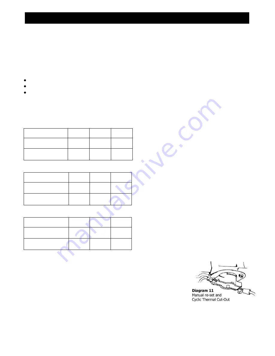
The unit includes a dual thermal cut-out (diagram 11) which is attached to                                                        
the heat exchanger tube.  It will switch off the heater elements if the water                                                                  

flow is reduced too much and the temperature goes above a set limit. 


The first stage cut-out is cyclic and will automatically reset as the water                                              
temperature falls.  The unit will then function normally again. 


The second stage cut-out when triggered needs to be reset manually inside the unit. 
This cut-out will only operate in exceptional circumstances (diagram 11) 


The unit can supply two outlets – for example, a shower and a basin, or up to two basins – but 

water from the unit will be shared between the outlets.  This is particularly important if a unit 
supplies a shower and a basin, as the basin should not be used while someone is using the shower. 
The unit is NOT to be fitted to a bath or kitchen sink other than for hand-washing purposes. 


HOW YOUR 

MULTIFLOW  

WORKS 

On average 
(12°C main water supply at 4 litres/minute) 

an outlet temperature of 46°C will be achieved. 


On average 
(12°C main water supply at 5 litres/minute) an 
outlet temperature of 43°C will be achieved.


On average 
(12°C main water supply at 6 litres/minute) an 

outlet temperature of 41°C will be achieved.


Summary of Contents for Multiflow 10.8kW

Page 1: ...h the user after installation and demonstration It should be kept in a safe place as you may need to refer to it for general instructions or future maintenance HEATSTORE MULTIFLOW UNVENTED INSTANTANEOUS WATER HEATER Installation and User Guide ...

Page 2: ... the current edition of BS 7671 the IEE Wiring Regulations and Part P of the Building Regulations in force at the time of installation Installations outside England and Wales must also conform to any local regulations in effect This appliance is intended to be permanently connected to the fixed electrical wiring of the mains supply with its own dedicated supply Ensure that the mains water supply m...

Page 3: ...namic Water Pressure Basin Shower Minimum Maximum Minimum Maximum Up to 9 5kW 10 psi 0 7 bar 69 kPa 150 psi 10 3 bar 1035 kPa 15 psi 1 1 bar 103 kPa 150 psi 10 3 bar 1035 kPa Up to 10 8kW 15 psi 1 1 bar 103 kPa 150 psi 10 3 bar 1035 kPa 20 psi 1 4 bar 138 kPa 150 psi 10 3 bar 1035 kPa Up to 12 0kW 20 psi 1 4 bar 138 kPa 150 psi 10 3 bar 1035 kPa 25 psi 1 8 bar 172 kPa 150 psi 10 3 bar 1035 kPa FIX...

Page 4: ... the backplate diagram 3 Feed the cable through the grommet before you fix the unit to the wall Fixing to the wall Undo the retaining nuts and take the front cover off the unit Hold the backplate in position against the wall whilst you mark the four fixing holes Drill the holes and fix the unit to the wall using the screws supplied Plumbing the unit WARNING IF A NON RETURN VALVE IS FITTED IN THE I...

Page 5: ...Connecting the unit to the pipes The inlet and outlet are clearly marked on the unit They each have a Ø15mm straight shank connections The unit comes with a service valve diagram 5 which should be fitted on the inlet of the unit The valve can be used to turn off the water supply to the unit if it needs servicing or to reduce the main supply flow if it is too high Fitting the attachments If the uni...

Page 6: ... 6 point X to X to enable 10mm and 16mm to be correctly installed No cutting is required for 6mm cable In all cases the outer sheath of the cable MUST project through the grommet diagram 6 if side entry is used This will prevent water getting into the unit Strip back the insulation on the LIVE brown or red and NEUTRAL blue or black mains wires about 8mm Strip back any insulation on the EARTH green...

Page 7: ...on light goes out then turn it back until the neon just comes on check the water temperature at the handset and if necessary turn the cold tap on and adjust to get the desired shower temperature WARNING YOU MUST REGULARLY INSPECT THE SHOWER HOSE FOR WEAR AND DAMAGE REPLACE IF NECESSARY OR EVERY TWO YEARS WITH OUR APPROVED PART WARNING IN ORDER TO MAINTAIN THE PERFORMANCE OF YOUR SHOWER YOU MUST DE...

Page 8: ...shed do not switch off the power if you are going to use the unit again shortly Shower Check that the power is switched on at the mains local isolator switch Turn on the hot or flow tap FULLY diagram 9 If the unit has been used recently run the water through for a few seconds to let the temperature settle down we advise you DO NOT enter the water flow during this time WARNING YOU MAY INITIALLY GET...

Page 9: ... the thermal cut out is operating A second outlet has been turned on Increase the supply water flow Make sure that the service valve is correctly adjusted Do not use the basin whilst using the shower Shower spray pattern deteriorates The shower handset is clogged Clean the handset using a descaling solution if required see page 9 We offer a technical advisory service on the telephone to installers...

Page 10: ...n supply to the INLET marked in blue Use a pump to boost the supply from a storage tank Reset it by opening the unit and pushing the button on the cut out diagram 11 Before you do this you must remove the cause of the problem Contact Heatstore Water too cold neon light on The power select screw is set to LO One element is not working The Power Supply Voltage has dropped Change the power select scr...

Page 11: ...s means that with the 12 0kW unit you can shower at 39 C with a flow rate of 5 litres minute in the middle of winter The unit includes a dual thermal cut out diagram 11 which is attached to the heat exchanger tube It will switch off the heater elements if the water flow is reduced too much and the temperature goes above a set limit The first stage cut out is cyclic and will automatically reset as ...

Page 12: ... NOT cover damage or defects arising from poor or incorrect installation improper use or lack of maintenance including the build up of limescale The unit MUST NOT be fitted to any type of thermostatic mixer valve or tap The unit MUST NOT be fitted to a bath or kitchen sink other than for hand washing purposes It is the responsibility of the installer to check that the installation parameters meet ...

Reviews: