background image

5

4 x

A-2046-12

Power Cable, 12” Length

4 x

A-2046-18

Power Cable, 18” Length

4 x

A-2046-24

Power Cable, 24” Length

5 x

PP-2059-01

Ethernet Cable, 12” Length

3 x

PP-2061-01

Ethernet Cable, 36” Length

4 x

A-2128-01

Power Distribution Board

1 x

A-2048-02

Power Jumper

X-Series 7-DoF Double Shoulder Arm Assembly Instructions

Summary of Contents for 7-DoF

Page 1: ......

Page 2: ... the operating temperature 10 to 50 Turn off power source before connecting or disconnecting actuator power Do not expose the actuator to permanent and strong magnetic fields The actuator must not be exposed to dusty or wet environments If actuator is under load abruptly removing the power connection can cause permanent damage Do not force screws into the bottom of the actuator X5 5mm tap depth X8...

Page 3: ... 16 Continuous limited by wiring 15 RPM Axis 2 Shoulder Pitch Default 2 x X8 16 90 to 90 avoid end effector collisions 15 RPM Axis 3 Shoulder Twist Default X8 16 Continuous limited by wiring 15 RPM Axis 4 Elbow Default X8 16 155 to 155 avoid end effector collisions 15 RPM Axis 5 Wrist 1 Default X5 4 Continuous limited by wiring 32 RPM Axis 6 Wrist 2 Default X5 4 Continuous limited by wiring 32 RPM...

Page 4: ... 2 x A 2091 02 3 x X5 4 5 x X8 16 X Series 7 DoF Double Shoulder Arm Assembly Instructions 1 x A 2043 01 2 x PM 2200 02 300mm 1 x A 2074 01 2 x A 2042 01R 1 x PM 2150 01L 1 x PM 2150 01R 1 x PM 2461 01 1 x PM 2149 02 2 x PM 2460 01 1 x A 2190 01 ...

Page 5: ...er Cable 18 Length 4 x A 2046 24 Power Cable 24 Length 5 x PP 2059 01 Ethernet Cable 12 Length 3 x PP 2061 01 Ethernet Cable 36 Length 4 x A 2128 01 Power Distribution Board 1 x A 2048 02 Power Jumper X Series 7 DoF Double Shoulder Arm Assembly Instructions ...

Page 6: ...6 X Series 7 DoF Double Shoulder Arm Assembly Instructions ...

Page 7: ...7 1 x PM 2200 02 300mm 1 x A 2039 03 X Series 7 DoF Double Shoulder Arm Assembly Instructions ...

Page 8: ...8 1 x PM 2200 02 300mm 1 x A 2039 03 1 x A 2038 03 X Series 7 DoF Double Shoulder Arm Assembly Instructions ...

Page 9: ...1 x 9 1 x X8 16 1 x A 2043 01 X Series 7 DoF Double Shoulder Arm Assembly Instructions ...

Page 10: ...1 x 10 1 x X8 16 X Series 7 DoF Double Shoulder Arm Assembly Instructions 1 x PM 2150 01L ...

Page 11: ...1 x 11 1 x X8 16 X Series 7 DoF Double Shoulder Arm Assembly Instructions 1 x PM 2150 01R ...

Page 12: ...1 x 12 Module output faces towards outside 1 x 1 x X Series 7 DoF Double Shoulder Arm Assembly Instructions 1 x PM 2149 02 ...

Page 13: ...1 x 13 Align with actuator output hub tick mark face parallel with tick mark and spring mounting hole pointed on same side 1 x 1 x X Series 7 DoF Double Shoulder Arm Assembly Instructions ...

Page 14: ...lign with actuator output hub tick mark flat surface with two tapped holes face towards x Axis direction specified on the bottom of the module X Series 7 DoF Double Shoulder Arm Assembly Instructions 2 x PM 2460 01 ...

Page 15: ...15 1 x 1 x X8 16 X Series 7 DoF Double Shoulder Arm Assembly Instructions 1 x PM 2461 01 ...

Page 16: ...1 x 16 1 x 1 x X Series 7 DoF Double Shoulder Arm Assembly Instructions ...

Page 17: ...with actuator output hub tick mark symmetric about tick mark with flat surface facing towards x Axis direction specified on the bottom of the module X Series 7 DoF Double Shoulder Arm Assembly Instructions 1 x A 2074 01 ...

Page 18: ...18 1 x 1 x 1 x X Series 7 DoF Double Shoulder Arm Assembly Instructions ...

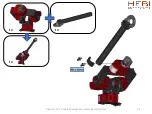
Page 19: ...19 1 x 1 x 1 x X8 16 X Series 7 DoF Double Shoulder Arm Assembly Instructions ...

Page 20: ...20 1 x 1 x 1 x Align with actuator output hub tick mark Tube aligns with tick mark X Series 7 DoF Double Shoulder Arm Assembly Instructions ...

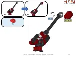
Page 21: ...21 1 x 1 x 1 x X5 4 X Series 7 DoF Double Shoulder Arm Assembly Instructions ...

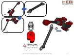
Page 22: ...22 1 x 1 x Align with actuator output hub tick mark X Series 7 DoF Double Shoulder Arm Assembly Instructions 1 x A 2042 01R ...

Page 23: ...23 1 x 1 x 1 x X5 4 X Series 7 DoF Double Shoulder Arm Assembly Instructions ...

Page 24: ...24 1 x 1 x Align with actuator output hub tick mark X Series 7 DoF Double Shoulder Arm Assembly Instructions 1 x A 2042 01R ...

Page 25: ...25 1 x 1 x 1 x X5 4 X Series 7 DoF Double Shoulder Arm Assembly Instructions ...

Page 26: ...26 X Series 7 DoF Double Shoulder Arm Assembly Instructions ...

Page 27: ...onnectors thru bore hole 1 at a time For more information visit docs hebi us 27 Spiral sleeving Wires that come from the previous joint should be inserted directly to actuator ports Wires that connect to the next joint should be threaded through the actuator s bore hole Power distribution boards are included to help daisy chain power connections These fit well within the tubes between actuators X ...

Page 28: ...st 2 Wrist 3 Power Cable Ethernet Cable Power Distribution Power Supply Power Jumper 12 Elbow 24 24 12 12 12 18 18 36 24 Shoulder Pitch 1 Base network 36 Shoulder Pitch 2 Shoulder Twist X Series 7 DoF Double Shoulder Arm Assembly Instructions ...

Page 29: ...29 1 x 1 x A 2090 02 2 x A 2091 02 Install cables before adding caps X Series 7 DoF Double Shoulder Arm Assembly Instructions ...

Page 30: ...30 HEBI Robotics 2019 X Series 7 DoF Double Shoulder Arm Assembly Instructions ...

Reviews: