9
The connectors comply with IEC 62852.
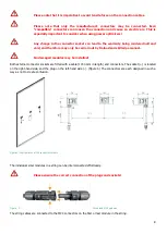
Please be sure to observe the requirements set out in DIN VDE 0298-3 for cable routing, in particular the smallest
permissible bending radii (Figure 6; R>5 x cable Ø) and the guidelines for cable fastening and routing.
Figure 6: Bending radii
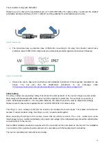
The connectors have a protection class of IP68 after connecting to the plug; the connector socket has a
protection class of IP65. Both components are permanently protected against environmental influences.
Figure 7: Protection class
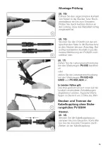
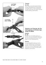
Pleasure be sure to observe the instructions and installation instructions of the respective manufacturer. See
Annex.
You
can
also
find
the
MultiContact
instructions
on
our
homepage
under
http://www.heckertsolar.com/de/downloads/partner-download-center/montage.html
Cable routing
Per string, 2 cables are required per string, that connect the solar generator to the inverter. Please use solar cables
that comply with the standard EN 50618 class 5 and the respective requirements. The minimum cross-section is
4mm². Cable losses should be < 1%. At greater distances, the cable cross-section must be adjusted accordingly.
Please be sure to observe the requirements set out in DIN VDE 0298-3 for cable routing.
The strings (+ and - cables) are fed into the inverter and connected to the DC inputs. The module connectors are
marked. To avoid conductor loops, the strings (+ and -) should be laid together.
When connecting the strings to the inverter, ensure that its polarity is correct. The + and - cables must not be
interchanged. Using a multimeter/voltmeter, the polarity and voltage of the individual strings should be verified before
connecting them to the inverter.
Only certified, suitable connectors are approved for the connection of the solar cables to the inverter. The installation
or connection of the inverters should be carried out in accordance with the manufacturer's instructions.
The inverter manufacturer’s instructions are binding.
Summary of Contents for NeMo 3.0
Page 1: ...Installation and operating manual www heckert solar com Status 08 2021...
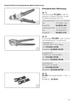
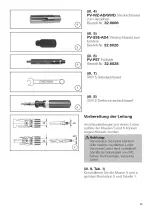
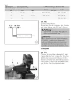
Page 12: ...12 Excerpt from MC4 crimping instructions Multi contact source...
Page 13: ...13...
Page 14: ...14...
Page 15: ...15...
Page 16: ...16...
Page 17: ...17 Heckert Solar GmbH Carl von Bach Stra e 11 D 09116 Chemnitz...


