background image

8

GB

THE HECO PHALANX MICRO 200A ACTIVE SUBWOOFER

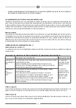
When connecting your loudspeaker, please make sure that everything has been switched off. Furthermore, 

make sure that all loudspeaker cables are connected to the proper poles, i.e. the positive pole for the 

output is connected to the positive pole for the input and the negative pole with the negative pole. Please 

also refer to your receiver’s/amplifier’s and loudspeakers’ instructions.

POSITIONING

The frequency range reproduced by the subwoofer cannot be pinpointed by the human ear. That‘s why 

positioning generally doesn‘t present any problems. However, it is preferable to place the speaker close 

to the front loudspeaker in front of the listening position. You should also make sure that the distance 

from the sides to items and walls is at least 30 centimetres and at least 20 centimetres from the rear as 

otherwise bass reproduction may be impaired.

THE SUBWOOFER’S OPERATING ELEMENTS (FIG. 1)

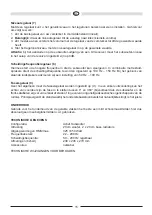
Mains connection (1)

The subwoofer is equipped with an integrated amplifier and needs to be connected to a mains outlet by 

means of the supplied mains cable. 

Mains switch (2), power LED (3), power switch (4)

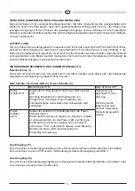
Mains switch ON

Mains switch OFF

Power switch 

ON

Subwoofer is in permanent operation, the power LED is 

green. 

Favourable setting for the reproduction of programmes 

with long quiet passages (this prevents the subwoofer from 

switching off unintention-ally).

Subwoofer switched off, 

Power LED off.

This is the setting for 

when subwoofer isn’t 
used over long periods.

Power 

switch 

AUTO

Subwoofer initially in standby mode, the power LED is red.

The subwoofer switches on automatically when it receives 

a signal from the re-ceiver, the power LED turns green. 

It automatically switches to standby after receiving no 

signals for around 15 min-utes, the power LED returns 

to red.

Recommended setting.

Line inputs (5)

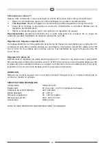
For connecting to level outputs on a receiver/amplifier (stereo mode), see Fig. 2.
For connecting to an AV receiver with low-level subwoofer output, see Fig. 3.

Line outputs (6)

For connecting to a receiver‘s/amplifier‘s low-level inputs (stereo mode), see Fig. 2, or for connecting a 

second subwoofer.

Summary of Contents for PHALANX MICRO 200A

Page 1: ...PHALANX MICRO 200A BEDIENUNGSANLEITUNG GARANTIEURKUNDE OWNER S MANUAL WARRANTY DOCUMENT MODE D EMPLOI CERTIFICAT DE GARANTIE...

Page 2: ...Verf gung stehenden R ckgabe und Sammelsystemen zu At the end of the product s useful life please dispose of it at appropriate collection points provided in your country Une fois le produit en fin de...

Page 3: ...4 D 7 GB 10 F 13 NL 16 I 19 E 22 25 S 28 RUS 32 CHN 35 J 39 Abbildungen Illustrations P...

Page 4: ...d zwischen Aktivsubwoofergeh use und Zimmerw nden oder anderen Gegenst nden z B M bel Regalw nde darf an keiner Seite 5 cm unterschreiten Die Aluminiumplatte bzw die K hlrippen des Verst rkers auf der...

Page 5: ...autem Verst rker handelt muss dieser ber das beiliegende Netzkabel an die Netzleitung angeschlossen werden Netz Schalter 2 Power LED 3 Power Schalter 4 Netz Schalter ON Netz Schalter OFF Power Schalte...

Page 6: ...ndlautsprecher zum Einsatz ist eine Einstellung von 50 Hz 100 Hz sinnvoll Phasenregler 9 Im Normalfall sollte der Phasenregler auf 0 eingestellt werden In seltenen F llen kann es jedoch von Vorteil se...

Page 7: ...objects e g furniture shelf units may not be less than 5 cm on any side The aluminium plate and cooling fins of the amplifier at the rear of the active subwoofer serve to cool the built in amplifier f...

Page 8: ...The subwoofer is equipped with an integrated amplifier and needs to be connected to a mains outlet by means of the supplied mains cable Mains switch 2 power LED 3 power switch 4 Mains switch ON Mains...

Page 9: ...dspeakers and to 50 to 100 Hz with stand loudspeakers Phase control 9 In normal use the phase control should be set to 0 However in rare cases it may be advantageous to vary the phase to between 0 and...

Page 10: ...t des liquides sur le subwoofer La distance entre le bo tier du subwoofer actif et les murs de la pi ce ou les autres objets par ex meubles parois d tag res doit tre au minimum de 5 cm La plaque d alu...

Page 11: ...est muni d un amplificateur int gr qui doit tre connect au secteur en utilisant le c ble de secteur fourni Interrupteur de puissance 2 DEL marche arr t 3 interrupteur marche arr t 4 Interrupteur mar...

Page 12: ...ag re la fr quence devrait tre r gl e entre 100 Hz et 150 Hz Si vous utilisez des enceintes colonne il est pr f rable de r gler la fr quence entre 50 Hz et 100 Hz R gulateur de phase 9 Normalement le...

Page 13: ...enerzijds en de wanden van de ruimte of eventuele andere objecten zoals meubels of kasten anderzijds mag aan alle kanten niet minder dan 5 cm bedragen De aluminiumplaat en de koelvinnen van de verste...

Page 14: ...vloed DE BEDIENELEMENTEN VAN DE SUBWOOFER AFB 1 Netaansluiting 1 Het betreft een subwoofer met ingebouwde versterker daarom moet deze met de meegeleverde kabel op het elektriciteitsnet worden aangeslo...

Page 15: ...esteld op 100 Hz 150 Hz Bij het gebruik van staande luidsprekers adviseren wij een instelling van 50 Hz 100 Hz Faseregelaar 9 Over het algemeen moet de fasesregelaar worden ingesteld op o In een enkel...

Page 16: ...anza o altri oggetti ad es mobili pareti attrezzate non deve essere inferiore di 5 cm su nessun lato La piastra in alluminio o le alette di raffreddamento dell amplificatore servono per il raffreddame...

Page 17: ...alla rete mediante il cavo fornito in dotazione Interruttore di rete 2 Spia di accensione 3 Interruttore di accensione 4 Interruttore di rete ON Interruttore di rete OFF Interruttore di accensione ON...

Page 18: ...are la frequenza su 100 150 Hz se si impiegano altoparlanti fissi consigliata un impostazione tra 50 100 Hz Regolatore di fase 9 Nel funzionamento normale si consiglia di posizionare il regolatore di...

Page 19: ...tes llenados de l quido No exponer nunca el subwoofer a salpicaduras y chorros de agua El subwoofer tampoco debe utilizarse para colocar floreros u otros recipientes llenados de l quido La distancia e...

Page 20: ...a que en caso contrario la reproducci n de sonidos bajos puede verse afectada LOS ELEMENTOS DE MANEJO DEL SUBWOOFER FIGURA 1 Conexi n a la red 1 Dado que se trata de un subwoofer con amplificador inco...

Page 21: ...s altavoces de estantes la frecuencia de separaci n deber ponerse en aprox 100 150 Hz Si se utilizan altavoces de pie se recomienda una frecuencia de 50 100 Hz Regulador de fases 9 Normalmente el regu...

Page 22: ...lados da caixa do subwoofer activo e as paredes ou outros objectos por exemplo m veis e estantes n o deve ser menor que 5 cm A placa de alum nio ou as aletas do amplificador no lado posterior do subw...

Page 23: ...Liga o rede el ctrica 1 Por tratar se aqui de um subwoofer com amplificador integrado preciso lig lo atrav s do cabo fornecido rede el ctrica Bot o de rede 2 LED de sinaliza o de for a 3 Bot o liga d...

Page 24: ...aso se utilize colunas recomenda se o ajuste de 50 Hz 100 Hz Regulador de fase 9 Normalmente o regulador de fase deveria ser ajustado em 0 Em alguns casos por m pode ser vantajoso variar a fase entre...

Page 25: ...5 cm vid n gon av sidorna F rst rkarens aluminiumplatta resp kylfl nsar p baksidan av den aktiva subwooferns anv nds f r kylning av den integrerade f rst rkaren och m ste ven ha 5 cm avst nd till alla...

Page 26: ...as till n tet med den bifogade kabeln N tstr mbrytare 2 Power lampa 3 Power str mbrytare 4 N tstr mbrytare ON N tstr mbrytare OFF Power str mbrytare ON Subwoofer r i kontinuerlig drift power lampan ly...

Page 27: ...las in p 100 Hz 150 Hz om st ende h gtalare anv nds kan en inst llning mellan 50 Hz 100 Hz rekommenderas Fasreglering 9 I normalfall ska fasregleringen st p 0 I vissa fall kan det vara l mpligt att va...

Page 28: ...28 RUS HECO 5 5 bassreflex...

Page 29: ...29 RUS 10 C 40 C HECO PHALANX MICRO 200A 30 20 1 1...

Page 30: ...30 RUS 2 3 4 ON OFF ON AUTO 15 Line 5 2 AV 3 Line 6 2 7 1 2 3 4 AV setup 0 8 100 150 50 100...

Page 31: ...31 RUS 9 0 0 180 TE 20 cm woofer 2 x 20 cm bass radiator RMS 325 650 22 200 50 200 x x 238 x 245 x 270...

Page 32: ...32 CHN HECO 5 cm 5 cm 10 C 40 C...

Page 33: ...33 CHN HECO PHALANX MICRO 200A 30 20 1 1 2 LED 3 4 15 5 2 AV 3 6 AV 2...

Page 34: ...34 CHN 7 1 2 3 4 AV 0 8 100 150 50 100 9 0 0 360 Powered subwoofer 20 cm woofer 2 x 20 cm bass radiator RMS Max 325 650 22 200 50 200 x x 238 x 245 x 270...

Page 35: ...35 J HECO 5 cm 5 cm 10 C 40 C...

Page 36: ...36 J HECO PHALANX MICRO 200A 30cm 20cm 1 1...

Page 37: ...37 J 2 LED 3 4 ON OFF ON LED OFF LED OFF AUTO LED LED 15 LED 5 2 AV 3 6 2 7 1 2 3 4 AV 0dB...

Page 38: ...38 J 8 100Hz 150Hz 50Hz 100Hz 9 0 0 360 Powered subwoofer 20 cm woofer 2 x 20 cm bass radiator RMS Max 325 650 Watt 22 200 Hz 50 200 Hz 238 x 245 x 270 mm...

Page 39: ...39 1...

Page 40: ...40 2...

Page 41: ...41 RECEIVER AMPLIFIER 3...

Page 42: ...d The guarantee period is not altered by the fact that we have carried out guarantee work 3 Unauthorized tampering with the equipment will invalidate this guarantee 4 Consult your authorized dealer fi...

Page 43: ...rial No Name und Anschrift des H ndlers Stempel Name and address of the dealer stamp K ufer Customer Name Name Stra e Street PLZ Ort City Land Country Nur g ltig in Verbindung mit Ihrer Kaufquittung N...

Page 44: ...Lise Meitner Str 9 D 50259 Pulheim Germany Tel 49 0 2234 807 0 Fax 49 0 2234 807 399 Internet http www heco audio de...

Reviews: