background image

Suprasetter A52/A75 - Installation

Suprasetter A52/A75

Installation

07/2019
Order No. PJ.999.0002/03

Suprasetter A52/A75

Summary of Contents for Suprasetter A52

Page 1: ...Suprasetter A52 A75 Installation Suprasetter A52 A75 Installation 07 2019 Order No PJ 999 0002 03 Suprasetter A52 A75 ...

Page 2: ...ubject to technical modifications and other changes with out notice Heidelberger Druckmaschinen AG assumes no responsibility for informa tion and description as far as third party products are concerned The information contained in this manual about performance and speed as well as technical data concerning application of our products is not legally binding as it does not consti tute a written con...

Page 3: ...Conductor Terminal 9 Power Switch with Emergency Stop Function 10 Automatic Cutouts 10 Safety Loop 11 Service Switch 11 Laser Safety 12 Definitions 12 General 12 Laser Standards and Regulations 13 Service and Maintenance 13 Laser Safety Goggles 14 Standards 14 Radio Interference Suppression 15 Approvals and conformity 15 Cleaning 16 Harmful Substances 16 Disposal 16 Glycol coolant 16 Overview of L...

Page 4: ...oading aid ramp 33 Pallet Installation Instructions 34 Installation Installation Suprasetter A52 A75 35 Delivery of the Suprasetter 35 Lifting the Suprasetter off the Pallet 35 Installation of the Suprasetter 37 Transport Safeguards 41 Checking Centering 47 Additional Work with Conveyor Option 48 Compressed Air Connection 51 Install Laser Module 52 Hose connections 52 Power Connection 57 Connectio...

Page 5: ... Top Loader Option 74 Format setting on insertion table bottom 74 Taller format guides for as many as 150 printing plates 74 Format setting on tray 75 Concluding Work 75 Install Web based Remote Service System via AXEDA 76 Testing 76 Set up material 76 Connecting the Online Processor to the Suprasetter 77 Technical Data Technical Data of Suprasetter A52 A75 79 Index ...

Page 6: ......

Page 7: ...es The following typographical conventions are used in this manual References to other chapters and sections are blue on the screen and underlined Example See section Symbols and Styles page 5 Quotes are used to indicate menus folders functions hardware conditions switch settings sys tem messages etc Example Set the switch to off Menus functions and sub functions are separated by Example Select Fi...

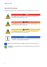
Page 8: ...rformed DANGER The DANGER signal word indicates a hazard with a high risk which if not avoided will result in death or severe injury WARNING The WARNING signal word indicates a hazard with a medium risk which if not avoided can result in death or severe injury CAUTION The CAUTION signal word indicates a hazard with a low risk which if not avoided can result in minor or moderate injury NOTICE The N...

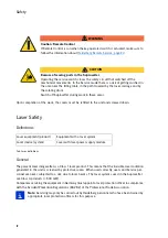
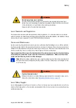
Page 9: ...ries through invisible high power laser radiation Follow the specified operational sequence when removing covers or other housing parts Risk of injury from sharp edges Plate edges can be sharp You can injure your hands if you do not wear protective gloves Put on pro tective gloves Safety Notes on Installation The Suprasetter including the output table to the processor when it is used may be instal...

Page 10: ...rotected against moisture In order to meet radio interference suppression requirements only screened data cables may be used Because the installation site must have clean conditions the Suprasetter may not be operated in sites where paper is being printed or paper finishing devices are running The required ambient conditions see Technical Data chapter must be observed for at least 12 hours after p...

Page 11: ...on ductor cable A separate PE cable green and yel low or only green with a cable cross section of at least 6 mm must be routed parallel to the power cable This cable 8 m is included in the Suprasetter shipment On the Suprasetter it must be con nected on the left to the rear brace Fig Fig 1 At the service tap it must be connected to a sepa rate PE terminal Fig 2 1 In addition you must make sure tha...

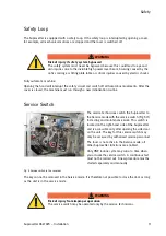
Page 12: ... right side of the Suprasetter WARNING Risk of injury from improper operation during an emergency stop The emergency stop circuits of Suprasetter machines are not connected to the emergency stop circuit of the online processor Press the emergency stop on the online processor to stop the online processor The automatic cutouts are located at the rear of the electric terminal box on the lower part F1...

Page 13: ...e this could lead to eye and skin injuries due to the invisible high power laser beam bruising caused by the optics carriage or tilting plate table or critical injuries caused by electric shocks The service technicians switch the Suprasetter to the Service mode with the service switch Fig 5 1 for testing and maintenance work This switch is located on the right hand side of the Suprasetter and is a...

Page 14: ...of the Professional Trade Association Note Servicing may only be carried out by Heidelberg personnel who have been trained by appropriate laser protection officers for this purpose WARNING Caution Remote Control If Remote Control is run when the key operated switch is actuated make sure to follow the information about Heidelberg Remote Service page 23 CAUTION Beware of moving parts in the Supraset...

Page 15: ...rotective covers must be checked for completeness Make sure that these covers do not show any cracks or other damages Note When the safety switches are open only the safety loop for the motive movement of the optics head can be bridged by the key switch The laser safety loop is not bridged as this is not necessary Laser Safety Goggles Laser safety goggles do not have to be worn as this is not nece...

Page 16: ...concerning the electromagnetic compatibility of devices Germany EN ISO 12100 Safety of machines Europe EN 1010 2 Safety of prepress machines Europe UVV Accident prevention regulation Germany EN ISO 13849 1 2008 Europe EN 60204 1 2006 Europe IEC 60204 1 2005 International EN 60950 1 2006 Europe IEC 60950 1 2005 International UL 60950 1 2007 USA CSA C22 2 No 60950 1 2007 Canada EN 55022 2003 Limit B...

Page 17: ...ence suppres sion regulations Compliance with radio interference suppression regulations can be assumed when the equipment in question is marked with the European Union mark of conformity CE and the instructions for instal lation operation and servicing are followed Approvals and conformity Tab Approvals and conformity EN 55024 1998 A2 2003 Europe EN 61000 6 2 2005 Europe CISPR 24 1997 A2 2002 Int...

Page 18: ...trations List of Threshold Values issued by the Federal Ministry of Labor and Social Affairs as well as the appropriate local regulations Disposal The Suprasetter must be disposed of in compliance with the relevant national regulations The Supra setter contains harmful substances It may not be disposed of together with household waste and must be handed over to an approved waste disposal company A...

Page 19: ...8 Note on conformance Labels on the outside Fig 6 1 Power switch Fig 6 2 Note on FCC conformance Fig 6 3 Laser Product Class 1 Fig 6 4 Type label Fig 6 5 CE mark of conformity Europe On the rear of the Suprasetter above the power switch Fig 6 1 Power switch symbols On the rear of the Suprasetter Fig 6 2 Note on FCC conformance ...

Page 20: ...tter Fig 6 3 Laser Product Class 1 On the outer rear of the Suprasetter and inside rear above the electronics box Fig 6 4 and Fig 14 5 Type label On the rear of the Suprasetter Fig 6 2 CE Mark of conformity Europe Labels on the inside 1 Laser Class 4 2 Beware of moving parts 3 Air inlet compressed air connection on a fully automated machine ...

Page 21: ...oving parts 1 Flash electrical hazard warning 2 Beware of moving parts 3 Laser Class 4 4 Filter replacement 1 Flash electrical hazard warning 2 Warning at the data cable input 3 Equivalent leakage current 4 High leakage current 5 Type label Fig 12 2 and Fig 13 2 At the machine front and at left and right chassis side ...

Page 22: ...f high voltage Fig 19 High leakage current Fig 14 3 At the rear on the mains terminal box Fig 12 1 and Fig 13 3 At the machine front and at left and right chassis side Fig 13 1 and Fig 14 1 On the rear on the power supply box and next to the power switch as well as on the chiller in the left door Fig 14 4 On the rear of the servo box ...

Page 23: ...2 Air inlet compressed air connection Fig 23 Laser Class 4 Fig 14 2 In front of the electronics nest On the laser module Fig 12 3 On the mounting bracket of the com pressed air connection on the right side only on a fully automated machine 0 8 MPa 8 bar 120 PSI On the laser module Aperture Class 4 laser ...

Page 24: ...Safety 22 Fig 24 Filter replacement Fig 13 4 On the filter unit ...

Page 25: ...autions During Remote Control Fig 25 Warning sign Even during Remote Control operation the machine coverings should be as complete as pos sible During Remote Control operation and open machine the service engineer must always be at the machine and ensure safety a warning sign Fig 25 must be attached to the machine and be clearly visible copy Fig 26 if necessary access of non authorized persons mus...

Page 26: ...Safety 24 Fig 26 Warning sign copy template ...

Page 27: ...ual functions GUI CTP User Interface for activating all single and interrelated functions Service terminal You can always stop the machine on site with the power switch or the EMERGENCY STOP button The machine s relatively small size and its construction allows a clear overview making hazard points plate loading table exposure cylinder laser module slide visible from almost any point around the ma...

Page 28: ...sing the confirmation key Fig 27 CTP User Interface The on site monitor also indicates that the key operated switch has been turned and the safety loop thus has been bypassed The yellow key Fig 27 1 in the bottom status bar of the figure indicates that the service key was turned i e the key operated switch is switched on The text box Fig 27 2 displays the following text RECORDER INFO 5011 This ser...

Page 29: ...ke note of this information when installing the device Floor Properties Make sure to inspect the ambient and floor conditions at the installation site prior to the delivery of the machine Install the machine on a level and solid floor Make sure the floor can bear the load when installing the machine Take appropriate measures to compensate for the settling of soft floors Tab Floor stability The flo...

Page 30: ...ERG machines are coated with VCI corrosion protection and sealed with PVC foil prior to shipment Underneath the foil a special atmosphere forms that protects the machine against corro sion A thermal shock occurs if the machine arrives at the customer s in a cold state due to low ambi ent temperatures and is brought to the relatively warm installation site in this state i e the dew point is reached...

Page 31: ...eath PVC or rubber Length 8 m when permanently connected length max 4 5 m when an L6 15P connector is fitted Note The outer diameter of the cable must not exceed 13 mm Plate Material Depending on the printing plate manufacturer and the used plate material thermal plates are also sensitive to light The quality of some plates may degrade even after a few minutes due to the UV por tion of white light...

Page 32: ...order No 00 580 6786 Adapter for Service Pushbutton Fig 3 Adapter for service pushbutton The pushbutton lets you start the pump in the chiller during coolant filling Description Service adapter X158 Part number BP 007 0052 Usage Chiller The service pushbutton replaces the operating button on X206 via this adapter when the hood is removed Description Adapter X206 Part number BP 007 1166 Usage Servi...

Page 33: ...nsertion Fig 5 Laser head insertion tool with thumb wheel Cable for connecting a PC to the Suprasetter For servicing only Description Adapter cable PC X113 Part number PR 581 7293 01 Usage Service monitor connection Device for tightening the spring that holds the inserted laser module Description Clamp Part number BV 011 9860 01 Usage Laser module ...

Page 34: ... Hose cutter Accuracy 0 05 Model e g Bosch DNM 60 L Description Electronic spirit level Part number 00 894 1437 Application Adjustment Hose cutter for rectangular cutting of hose ends up to 12 mm Ø Description Hose cutter TK 3 Part number 00 894 1053 Application Hose connections ...

Page 35: ... A75 Installation 33 Unloading aid ramp Fig 8 Ramp Note See the chapter Tools in the service manual for further service tools Description Unloading aid ramp Part number BV 013 8185 Usage Installation lifting the Suprasetter off the pallet i i ...

Page 36: ...Installation Preparation 34 Pallet Installation Instructions ...

Page 37: ...aset ter off the pallet one for fork lift trucks and one for pallet trucks You must remove the Suprasetter from the pallet in several steps with a pallet truck if no fork lift truck is available The blocks packed on the sides of the Suprasetter are needed if a pallet truck is used see Installa tion Instructions image 16 and 17 see page 34 The spacers image 9 thru 13 are located on the left and rig...

Page 38: ...upper part of the covering towards you magnetic lock and lift it out at the bottom Loosen the 3 clips in the rear covering by 1 4 turn and take off the rear panel Take the Suprasetter off the pallet according to Information for the Technician in the installation instructions attached to the machine ...

Page 39: ... 5 mm between rollers and floor Use a spirit level when aligning the Suprasetter by adjusting the height of the 3 feet WARNING Risk of injury from buckling feet when pushing the machine The feet Fig 4 1 are rubber coated to prevent wandering of the machine Once on its feet the Suprasetter may no longer be moved Moving the machine by force will bend the feet Place a spirit level on the milled part ...

Page 40: ...l doors and place the spirit level on the cast chassis Align in horizontal direction by adjusting the front feet of the cast chassis Pull off connector X206 Fig 7 2 and Fig 8 2 Only for a semi automatic device Loosen the brackets on both sides of the Suprasetter Fig 7 1 not applicable for DTL see Fig 8 ...

Page 41: ...s if Autoloader used Fig 10 Cover fastening fully automatic machine Only with DTL Remove the screws on both sides Fig 9 1 4x Unscrew the screws Fig 9 2 two each on left and right and pull out the paper chute Only with DTL Open cover and remove 3 screws Fig 10 1 ...

Page 42: ...Installation 40 Fig 11 Cover rail Remove 3 screws each on both sides of the cover Fig 11 1 Take off the cover with 2 persons ...

Page 43: ... right NOTICE Make sure to heed the order to avoid damages The transport safeguards on the chassis must be removed last Keep all transport safeguards in a safe place On the right side Cut and remove the cable tie of the punch waste box Fig 12 only with the Punch option Loosen the four screws from the bracket and remove the bracket Fig 13 1 ...

Page 44: ... Swivel table left Cut open and remove the cable tie securing the transport roller Fig 14 1 In addition for a semi automatic device Cut open and remove the cable tie securing the gate Cut open and remove the cable ties for NIP roller Fig 15 1 and VCT bar Fig 15 2 On the left side Loosen the four screws from the bracket and remove the bracket Fig 16 1 i i ...

Page 45: ... left Fig 19 Transport safeguard Feed motor Cut open and remove the cable tie securing the roller Fig 17 1 In addition for a semi automatic device Cut open and remove the cable tie securing the gate Cut open and remove the cable ties for NIP roller Fig 18 1 and VCT bar Fig 18 2 Loosen the four screws Fig 19 1 of the feed motor and remove the bracket i i ...

Page 46: ...port safeguard Locking screw Fig 22 Transport safeguard Exhaust pump Loosen the lock nut Fig 20 1 on the drum Undo the screw Fig 21 1 and the cable tie Fig 21 2 Only with the Exhaust option Unscrew four screws and remove the plate secur ing the exhaust pump Fig 22 1 ...

Page 47: ...haust filter Fig 24 Transport safeguard Laser carriage Only with the Exhaust option Cut open and remove the four cable ties Fig 23 1 on the clamps of the exhaust filter At front of the Suprasetter Loosen the four screws Fig 24 1 and remove the bracket securing the laser carriage ...

Page 48: ...safeguard Chassis bottom Loosen the screws of the four brackets Fig 25 1 and remove the brackets Cut open the cable ties Fig 25 2 and remove them Transport safeguards for the chassis On the left and right side of the Suprasetter i e 2x2 transport safeguards Loosen screws 3 to 4 turns from above Fig 26 Do not fully unscrew these screws Remove the screws Fig 27 with 2 washers each at each chassis co...

Page 49: ...9 Centering Screw down the two chassis feet Fig 28 1 at the front of the Suprasetter to slightly raise the Supra setter Remove the spacer sleeves Fig 27 1 Pull out the brackets Fig 26 1 sideways under neath the chassis on the left and right side of the Suprasetter The ring Fig 29 1 should be in the center on both sides in the recess Fig 29 2 The recess is rect angular on one side of the Suprasette...

Page 50: ...t and right Fig 31 1 loosely into the conveyor Hook the conveyor Fig 32 1 into the holders with the two combination screws align them centrally and fasten it with the six combination screws M4x10 Make absolutely sure The two buffers Fig 33 1 on the conveyor must always rest on the module if any below it or the conveyor must be propped up with a suitable support If this is not done the entire weigh...

Page 51: ...69 Fit the cover Fig 35 1 and the bezel Fig 35 2 Route adapter X22 X69 to the electronics box Start at the swivel area of the rotary table the opto switch lug and secure with cable ties The cable between connector X69 Fig 36 1 and cable tie Fig 36 2 should be 220 mm long Plug connector X69 Fig 36 1 to motor M80 ...

Page 52: ...nd X22 Route the adapter Fig 37 1 to the electronics box Make sure for EMC reasons to route the cables as close to the sheet metal as possible Plug connector X22 Fig 38 22 to the DSC board Plug connector X16 Fig 38 16 from the sensor to the DSC board ...

Page 53: ...ed Air Connection Only with the Fully Automated or Double Table option Fig 39 Compressed air connection Fig 40 Adjusting valve Route and connect the compressed air hose Fig 39 1 behind the right door Set the pressure to 6 bar with the adjusting valve Fig 40 1 ...

Page 54: ...tage When the Suprasetter is switched on parts in the device are live The Suprasetter must be in an off state for subsequent work NOTICE Sensitive contacts Make sure not to touch the contacts Fig 41 2 NOTICE Sensitive lens Do not touch the lenses Take the laser module out of the packaging and align the hoses as shown in Fig 41 1 Check that the electric contacts are undamaged i i ...

Page 55: ...The distance between the cap Fig 42 4 and the connector is then approx 1 mm Please note that just like with the compressed air connection you must overcome a resistance twice with the connections on the laser module 1 with the collet and 2 with the O ring You can tell that a hose was pushed into the con nector far enough if the visible part of the metallic sleeve is smaller than 5 mm Fig 43 Again ...

Page 56: ... foil from the lens Clean the module slot with a lint free cloth if necessary Make sure that the spring Fig 44 1 enters the hole Fig 44 2 when you are inserting the laser module NOTICE Sensitive lens Do not touch the lens Take the eccentric Fig 45 1 from the package fit it onto special purpose tool BV 011 9860 01 and screw tight NOTICE Risk of breakage Do not use force the pin could break ...

Page 57: ...by approx 1 2 turn in clockwise direction as far as the stop Undo the eccentric with the small wheel of the insertion tool it remains in the Suprasetter NOTICE Leaking coolant Immediately wipe off any spilled coolant Make sure no coolant reaches the PCB Fig 44 3 Take out the hose Fig 47 1 To pull a hose out of its holder first push the hose slightly into the holder then hold the ring Fig 47 2 in t...

Page 58: ...6 Fig 48 Fit hoses Fit connector X381 again Vigorously push the hoses Fig 48 2 into the cou plings Fig 48 1 as far as the stop Fig 42 NOTICE Beware of short circuit Do not tilt the laser module while it is energized ...

Page 59: ...for the EU power cable Use the bottom cable clamp for the US power cable Remove the cable clamp that is not needed Guide the power cable up to the terminal block by means of strain relief Fig 51 1 and through the cable clamp Fig 49 2 Connect the power cable to the terminal block and the PE wire to the sheet metal Fig 49 3 Fasten the cover plate of the mains terminal box back on again with the thre...

Page 60: ...Installation 58 Fig 51 Power cable strain relief Tighten the strain relief for the power cable Fig 51 1 ...

Page 61: ...energized only Connect the GUI cable from the 2nd network adapter in the PC to X171 Fig 52 1 Connect the Gigabit cable from the interface board in the PC to X309 Fig 52 2 As an alternative to the Gigabit connection you can also use the LVDS port from the interface board in the PC on X300 Fig 52 3 However preference is to be given to the Gigabit connection Fasten the Gigabit or LVDS cable and if an...

Page 62: ...lose the side panel again Connect the Gigabit cable to the GBIT port Fig 54 3 As an alternative to the Gigabit connection you can also connect the cable to the LVDS port Fig 54 4 However preference is to be given to the Gigabit connection Connect the GUI cable Ethernet tagged 00 782 1027 cross over to the second network adapter Fig 54 2 You can invoke the terminal via the GUI Plug in the power plu...

Page 63: ...Installation Suprasetter A52 A75 Installation 61 Fig 55 Network Fig 56 Network Connections Select the network Select Network Connections and select Local Area Connection 2 ...

Page 64: ...Installation 62 Fig 57 LAN Connection 2 Properties Fig 58 IP address Also enable Show icon in notification area when connected Click Properties and specify the IP address ...

Page 65: ...the renamed item and select Advanced Settings in the Advanced menu In Connections select LAN In house and move it to the top of the list using the arrow buttons to the right then confirm with OK Check after the first PC start if the existing PC has correctly detected the second hard disk required for the page buffer The volume name must be PAGEBUFF ...

Page 66: ... and must also be re attached there after installation Fig 62 The USB stick contains the software ver sion that is required for installation of the Supra setter If a more recent software is available at the time of installation installation can be updated subse quently In addition the USB stick contains the parameter database as delivered as data_all txt NOTICE It is vital to use only the software...

Page 67: ...etermine and set the system configuration in the CTP User Interface in Service Configuration Installing DIAG Suprasetter Attach the USB stick Cancel the setup program for the Suprasetter operating software if it should start automatically In Windows Explorer start the Diagnostic SW Suprasetter_Diag SETUP EXE file Confirm the queries The setup copies all the components of the diagnostic software in...

Page 68: ..._A52_A74 from the Start menu The Speedway Target Configuration window in which you must set Main Target to active appears on top of the large diagnosis window Use the Select button to open C Program Files x86 Heidelberg CTP Diagnose Supraset ter_A75 DIAG Suprasetter_A75 Diag Supraset ter tdb In the Interface Settings dialog select Supraset ter_A52_74 as the target Select Ethernet as the type In Et...

Page 69: ... is the risk of an electric shock when wiping off coolant Avoid dripping water Be careful when handling the coolant near energized components CAUTION Caution Risk of injury to eyes or skin from Glysantin Heed the warnings given in the safety data sheets for the anticorrosive or the notes on the coolant container Make sure to wear protective gloves and goggles when handling coolant NOTICE Water con...

Page 70: ... provided by customer 2 Funnel Part of the Suprasetter 3 Filler hose 00 471 0343 Part of the Suprasetter 4 Vent hose PL 485 7496 Part of the Suprasetter 5 Container for liquids 00 471 0343 Container free of chemical resi dues Volume At least 2 liters Not included in the Suprasetter shipment Must be provided by customer 6 Glysantin G48 00 580 6786 1 can 1 5 liters supplied with Suprasetter 7 Water ...

Page 71: ... sure that the mixture is clean because even small amounts of dirt can cause changes in the coolant and can damage the components in the cooling circuit The numbers correspond to the items in the Table Filling above 3 Fit funnel Fig 68 2 onto the filler hose Fig 68 3 4 Prepare coolant made up of 1 part Glysantin 3 parts chlorine free drinking water 25 in the measuring cup Fig 68 1 Initial filling ...

Page 72: ...crews from above for the bracket Fig 68 3 to which the filler hose is fastened 6 Plug X158 of the service pushbutton see position 9 in Table Filling 3 to X158 on the chiller PCB Fig 69 1 7 Fit bracket again 8 Set switch 3 Fig 70 3 of microswitch S2 down to OFF Fig 71 DIP Function 1 S2 1 Chiller 2 S2 2 Program 3 S2 3 Test mode 4 S2 4 Buzzer i i ...

Page 73: ...s while filling in coolant The pump in the chiller operates as long as the pushbutton is kept pressed and starts filling the chiller circuit The topmost red LEDs H1 and H2 Fig 69 2 on the chiller PCB now indicate the filling level LOWER LEVEL H2 and UPPER LEVEL H1 have been reached when both LEDs are lit while the but ton is being pressed 15 Release the service button and wait for ca 3 seconds unt...

Page 74: ...nnel 22 Remove the cloth Fig 72 2 23 Remove the bracket Fig 68 3 disconnect the service pushbutton from X158 and reattach the bracket with the two screws again 24 Close the hose coupling Fig 71 4 of the vent hose Fig 71 2 with the plug Fig 71 5 and fas ten it on the chiller again Fig 71 3 25 Switch on the power switch of the Suprasetter and boot the Suprasetter with the pushbutton The chiller issu...

Page 75: ...73 Paper chute Fig 74 Net Insert the paper chute Fig 73 1 using the two rails Fig 73 arrows Align the paper chute with the closed front cover ing and then secure with four screws Thread both stay tubes into the collecting net Hook the net Fig 74 1 into both rails Fig 74 arrows ...

Page 76: ...g to the size required For operation with the insertion table only with out a tray the format guides Fig 76 1 can be replaced by format guides with a greater side length part of the accessories To do this move the format guides towards the center to the larger opening and remove upwards Insert the format guides with the taller side length and set them according to the size required The maximum for...

Page 77: ...el Fig 3 Heed the direction of the brackets during hood installation The brackets point to the outside Fit the cover Fig 7 and Fig 11 remove the service pushbutton if used and plug the connector of the operating button to X206 Install the front cover Fig 2 Switch on the Suprasetter With the Suprasetter switched off check that the laser module is seated correctly unhook spring reposition module tig...

Page 78: ...ons on how to do this The chapter Instructions for Testing provides in depth information on how to test printing plates Installation is described in the Intranet in Products Service Systemservice Remote Service Intranet Only registered Heidelberg employees and part ners have access to this portal Employees and partners who are not registered must request the appropriate access documents More detai...

Page 79: ...ht Fig 79 OLP connection X121 in the Suprasetter Fig 80 OLP connection point for ground connection NOTICE Sensitive electronics Make sure to deenergize the Suprasetter as well as the online processor prior to connecting any cables Connect the online processor data cable to X121 Fig 79 1 in the Suprasetter Connect the equipotential bonding cable from the online processor to the ground point Fig 80 ...

Page 80: ...PDF to be found in Sherlock in PT000 Computer to Plate PL000 Suprasetter SRH Service Manual Suprasetter Maintenance and Repair Repair Removal and Installation Online Processor Interface describes the interface to the online processor in detail i i ...

Page 81: ... W standby 4 W Heat Radiation max 2500 kJ h typically 1980 kJ h Power save 970 kJ h stand by 14 kJ h Compressed air con nection max 8 bar 120 PSI min 6 bar 90 PSI at the input min 150 l min max 5 µm dry oil free compressed air Connection for fully automatic machine only Permanent air volume Particle size Ambient conditions operation 17 C to 30 C 700 mbar to 1060 mbar 30 to 70 Temperature Air press...

Page 82: ...Technical Data 80 Resolution 1000 pixels cm 2540 dpi Type Value Comment ...

Page 83: ...nstructions 34 Intended use 7 L Labels 17 Laser head insertion tool 31 Laser module 52 LEDs 72 M Machine feet 37 Microswitch S2 70 O On line Processor 77 Options 48 73 74 P Pallet 34 35 Paper chute 73 PC connection 59 PCB 00 785 1151 70 Plate material 29 Power cable 8 29 Power connection 57 Power supply 8 Power switch 10 Protective conductor connection 9 57 R Remote Service 23 S S2 70 Safety loop ...

Page 84: ......

Page 85: ......
Page 86: ...egistered trade marks of Heidelberger Druckmaschinen AG in the United States and other countries Adobe and PostScript and Acrobat are either registered trademarks or trademarks of Adobe Systems Incorporated in the United States and or other countries PANTONE and Hexachrome are registered trademarks of Pantone Inc All other trademarks are property of their respective owners Subject to technical mod...

Reviews: