161
HEIDENHAIN TNC 426 B, TNC 430
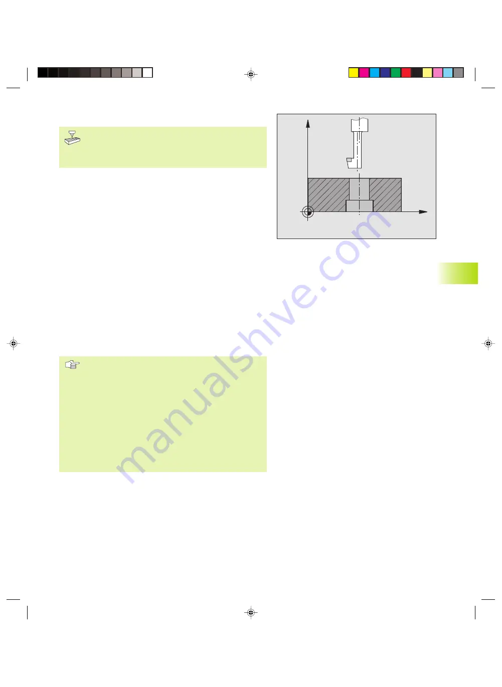
BACK BORING (Cycle 204)
Machine and TNC must be specially prepared by the
machine tool builder to perform back boring.
Special boring bars for upward cutting are required for
this cycle.
This cycle allows holes to be bored from the underside of the
workpiece.
1
The TNC positions the tool in the tool axis at rapid traverse FMAX
to set-up clearance above the workpiece surface.
2
The TNC then orients the spindle to the 0° position
with an oriented spindle stop, and displaces the tool by the off-
center distance.
3
The tool is then plunged into the already bored hole at the feed
rate for pre-positioning until the tooth has reached set-up
clearance on the underside of the workpiece.
4
The TNC then centers the tool again over the bore hole, switches
on the spindle and the coolant and moves at the feed rate for
boring to the depth of bore.
5
If a dwell time is entered, the tool will pause at the top of the
bore hole and will then be retracted from the hole again. The TNC
carries out another oriented spindle stop and the tool is once
again displaced by the off-center distance.
6
The TNC moves the tool at the pre-positioning feed rate to the
set-up clearance and then, if entered, to the 2nd set-up clearance
with FMAX.
Before programming, note the following:
Program a positioning block for the starting point (hole
center) in the working plane with RADIUS
COMPENSATION R0.
The algebraic sign for the cycle parameter depth
determines the working direction. Note: A positive sign
bores in the direction of the positive spindle axis.
The entered tool length is the total length to the
underside of the boring bar and not just to the tooth.
When calculating the starting point for boring, the TNC
considers the tooth length of the boring bar and the
thickness of the material.
8.2 Dr
illing Cy
cles
X
Z
kkap8.pm6
30.06.2006, 07:03
161
www.EngineeringBooksPdf.com
Summary of Contents for TNC 426 B
Page 3: ...BAUSKLA PM6 30 06 2006 07 03 2 www EngineeringBooksPdf com ...
Page 4: ...BAUSKLA PM6 30 06 2006 07 03 3 www EngineeringBooksPdf com ...
Page 6: ...CINHALT PM6 30 06 2006 07 03 2 www EngineeringBooksPdf com ...
Page 16: ...CINHALT PM6 30 06 2006 07 03 12 www EngineeringBooksPdf com ...
Page 17: ...Introduction 1 Dkap1 pm6 30 06 2006 07 03 1 www EngineeringBooksPdf com ...
Page 29: ...Manual Operation and Setup 2 Dkap2_3 pm6 30 06 2006 07 03 13 www EngineeringBooksPdf com ...
Page 83: ...Programming Tools 5 Fkap5 pm6 30 06 2006 07 03 67 www EngineeringBooksPdf com ...
Page 106: ...Fkap5 pm6 30 06 2006 07 03 90 www EngineeringBooksPdf com ...
Page 107: ...Programming Programming Contours 6 Gkap6 pm6 30 06 2006 07 04 91 www EngineeringBooksPdf com ...
Page 165: ...Hkap7 pm6 30 06 2006 07 03 150 www EngineeringBooksPdf com ...
Page 166: ...Programming Cycles 8 kkap8 pm6 30 06 2006 07 03 151 www EngineeringBooksPdf com ...
Page 253: ...kkap8 pm6 30 06 2006 07 04 238 www EngineeringBooksPdf com ...
Page 265: ...LKAP9 PM6 30 06 2006 07 04 250 www EngineeringBooksPdf com ...
Page 266: ...Programming Q Parameters 10 MKAP10 PM6 30 06 2006 07 04 251 www EngineeringBooksPdf com ...
Page 297: ...MKAP10 PM6 30 06 2006 07 04 282 www EngineeringBooksPdf com ...
Page 298: ...Test Run and Program Run 11 NKAP11 PM6 30 06 2006 07 04 283 www EngineeringBooksPdf com ...
Page 312: ...MOD Functions 12 Okap12 pm6 30 06 2006 07 04 297 www EngineeringBooksPdf com ...
Page 332: ...Tables and Overviews 13 Pkap13 pm6 30 06 2006 07 04 317 www EngineeringBooksPdf com ...


