background image

REPLACEMENT PARTS  

(refer to page 12 & 13)

Not all components of the jack are replacement items, but are illustrated as a convenient reference of location and 

position in the assembly sequence. When ordering parts, give model number, part number and parts description. Call 

or write for current pricing: Hein-Werner Customer Support, 10939 N. Pomona Ave. Kansas City, MO 64153. Phone: 

(816)891-6390;   E-mail: customerservices@heinwerner-automotive.com

Replacement Parts for HW93659 Frame

Figure 9 - Parts Illustration for HW93659 Frame

Grease pin and clevis at assembly before

installing power unit and roll pin.

16

17

6

21

23

22

24

1

5

1 4

9

1

3

12

11

3

19

10

1

18

5

2

20

4

7

8

Item

Part#

Description

Qty. 

1

239603

Handle Assembly

1

2

239604

Pump Handle Weldment

1

3

239605

Handle Lock and Hooks

1

4

239606

Retaining Ring, E,  3/8”

4

5

239607

Handle Pivot Shaft, 3/8”

1

6

239608

Hydraulic Unit

1

7

239609

Link

2

8

239610

Pump Pin

2

9

239611

Roll Pin, 1/4”Dia x 1-3/8”L

1

10

239612

Capscrew, Self- Locking 

1/2-20UNFx1 1/2L

1

11

239613

Trunnion

2

12

239614

Retaining Ring, E, 3/4”

2

Item

Part#

Description

Qty.

13

239615

Washer, 1” OD

2

14

239616

Wheel, 3” Dia.

2

15

239617

Axle, 3/4”Dia

2

16

239618

Lift Pad

1

17

239619

Frame

1

18

239620

Lift Pad Pin 9/16D x3 3/8L

1

19

239627

Quick Release Pin, 5/16D

1

20

239602

Pipe Plug, 1/8”

1

21

239628

Knob

1

22

239601

Roll Pin, 1/8D x 1 5/8L

1

23

239625

Roll Pin, 5/32D x 3/4L

1

24

239626

Spring, Modified Torsion

1

-

239893

Label Kit

-

12

Summary of Contents for HW93659

Page 1: ...tive com HW93659 M0 rev 11 07 This is the safety alert symbol It is used to alert you to potential personal injury hazards Obey all safety messages that follow this symbol to avoid possible injury or...

Page 2: ...5 3 Select appropriate Support Stands and Bring Them to the Immediate Work Area 6 4 Prepare the Surrounding Area Before Using the Jack 6 5 Identify a Lift Point Prepare the Load for Lifting and Chock...

Page 3: ...s running NEVER use this jack in conjunction with any other jack or lift NEVER use this jack to raise one side or end of a forklift unless the other side or end of the forklift is in contact with the...

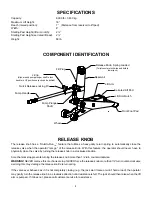
Page 4: ...re than 1 2 turn counterclockwise WARNING NEVER remove this mechanical stop NEVER force the release knob more than 1 2 turn counter clockwise as doing this may damage the release knob s return spring...

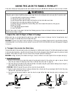
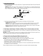
Page 5: ...mer service at 816 891 6390 NEVER use a jack that appears damaged in any way 2 Transport the Jack to the Work Area Transport the jack to the work area by either a wheeling it or b lifting and carrying...

Page 6: ...ands and Bring Them to the Immediate work Area It is important that appropriate support stands are used Hein Werner manufactures support stands that are made speci cally for forklifts WARNING Use appr...

Page 7: ...eled forklift from the 2 wheeled end or from the side NEVER use the jack to raise all four wheels of the forklift from the oor NEVER raise the forklift higher than 1 4 its tread width see Figure 4 Fig...

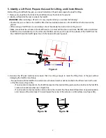
Page 8: ...ocated on top of the lift arm WARNING NEVER lift the forklift by its counterweight WARNING NEVER lift the forklift in a manner that is counter to the manufacturer s recommendations 6 Raise the Forklif...

Page 9: ...RNING Turn the release knob slowly to prevent the possibility of the jack from kicking out from under the forklift 4 Lower the jack completely and move the jack and chocks away from the work area INSP...

Page 10: ...If they are not contact Hein Werner for replacement labeling Wash external surfaces of jack labels and decals with a mild soap solution 2 Lubricate all rotating and sliding portions of the jack monthl...

Page 11: ...on of this manual Release is open gently turn the release knob in a clockwise direction until resistance is felt See the Release Knob Hold To Run FeatureTM section of this manual Overloaded use larger...

Page 12: ...1 4 9 1 3 12 11 3 19 10 1 18 5 2 20 4 7 8 Item Part Description Qty 1 239603 Handle Assembly 1 2 239604 Pump Handle Weldment 1 3 239605 Handle Lock and Hooks 1 4 239606 Retaining Ring E 3 8 4 5 23960...

Page 13: ...ing E 7 16Dia 1 13 238013 Ball 1 8 Dia 1 14 238014 Cylinder Cap 1 15 238015 O ring 2 1 16OD x 1 7 8ID 2 16 238016 Piston Segment 3 17 238017 Cylinder 1 18 238018 Reservoir Tube Weldment 1 19 238019 Pi...

Page 14: ...EVER 3 ANY IMPLIED WARRANTIES INCLUDING WITHOUT LIMITATION THE IMPLIED WARRANTIES OF MERCHANTABILITY AND FITNESS FOR A PARTICULAR PURPOSE SHALL BE LIMITED TO TWO YEARS OTHERWISE THE REPAIR REPLACEMENT...

Reviews: