background image

5. Identify a Lift Point, Prepare the Load for Lifting, and Chock Wheels

Before lifting a forklift with the jack, you need to identify a lift point and prepare the load for lifting.
1. Remove any load from the forks of the forklift and lower the forks to the ground.

2. Identify a lift point at the rear or side of the forklift.
   

WARNING!


When selecting a lift point, it is very important that you consider the following:

   • Position the jack so that, as the forklift is lifted, the load will be balanced on the forklift tires that remain on the 

     ground.
   • When raising a forklift from one end, always chock the wheels that will remain on the ground.
   • Make sure at least two wheels of the forklift remain in contact with the floor at all times. NEVER raise a 3-wheeled 

     forklift from the 2-wheeled end or from the side. NEVER use the jack to raise all four wheels of the forklift from the 

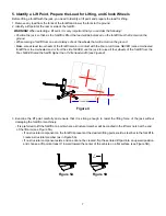
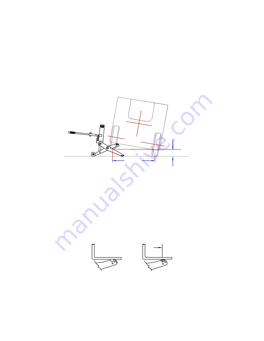
     floor. NEVER raise the forklift higher than 1/4 its tread width (see Figure 4).

Figure 4

Tread Width

Height

3.  Examine  the  lift  point  carefully  and  ensure  that  it  is  strong  enough  to  resist  the  lifting  force  of  the  jack  without 

damaging the forklift or machinery.

  • If is preferred to lift the forklift at a point where a structural member will be cradled in the lift arm notch at the end 

      of the lift arm (see Figure 5A).


• If no structural component on the forklift is present at the desired lifting point, weld a steel bar to the forklift to  


  create a structural member (as in Figure 5A).


• If no structural component exists and one cannot be created, flip the serrated lift pad into an upward position  


  and choose a lift point at least 3” inward toward the center of the vehicle on a flat surface (see Figure 5B).

Figure 5A                     Figure 5B

7

3" 

Min.

Summary of Contents for HW93659

Page 1: ...tive com HW93659 M0 rev 11 07 This is the safety alert symbol It is used to alert you to potential personal injury hazards Obey all safety messages that follow this symbol to avoid possible injury or...

Page 2: ...5 3 Select appropriate Support Stands and Bring Them to the Immediate Work Area 6 4 Prepare the Surrounding Area Before Using the Jack 6 5 Identify a Lift Point Prepare the Load for Lifting and Chock...

Page 3: ...s running NEVER use this jack in conjunction with any other jack or lift NEVER use this jack to raise one side or end of a forklift unless the other side or end of the forklift is in contact with the...

Page 4: ...re than 1 2 turn counterclockwise WARNING NEVER remove this mechanical stop NEVER force the release knob more than 1 2 turn counter clockwise as doing this may damage the release knob s return spring...

Page 5: ...mer service at 816 891 6390 NEVER use a jack that appears damaged in any way 2 Transport the Jack to the Work Area Transport the jack to the work area by either a wheeling it or b lifting and carrying...

Page 6: ...ands and Bring Them to the Immediate work Area It is important that appropriate support stands are used Hein Werner manufactures support stands that are made speci cally for forklifts WARNING Use appr...

Page 7: ...eled forklift from the 2 wheeled end or from the side NEVER use the jack to raise all four wheels of the forklift from the oor NEVER raise the forklift higher than 1 4 its tread width see Figure 4 Fig...

Page 8: ...ocated on top of the lift arm WARNING NEVER lift the forklift by its counterweight WARNING NEVER lift the forklift in a manner that is counter to the manufacturer s recommendations 6 Raise the Forklif...

Page 9: ...RNING Turn the release knob slowly to prevent the possibility of the jack from kicking out from under the forklift 4 Lower the jack completely and move the jack and chocks away from the work area INSP...

Page 10: ...If they are not contact Hein Werner for replacement labeling Wash external surfaces of jack labels and decals with a mild soap solution 2 Lubricate all rotating and sliding portions of the jack monthl...

Page 11: ...on of this manual Release is open gently turn the release knob in a clockwise direction until resistance is felt See the Release Knob Hold To Run FeatureTM section of this manual Overloaded use larger...

Page 12: ...1 4 9 1 3 12 11 3 19 10 1 18 5 2 20 4 7 8 Item Part Description Qty 1 239603 Handle Assembly 1 2 239604 Pump Handle Weldment 1 3 239605 Handle Lock and Hooks 1 4 239606 Retaining Ring E 3 8 4 5 23960...

Page 13: ...ing E 7 16Dia 1 13 238013 Ball 1 8 Dia 1 14 238014 Cylinder Cap 1 15 238015 O ring 2 1 16OD x 1 7 8ID 2 16 238016 Piston Segment 3 17 238017 Cylinder 1 18 238018 Reservoir Tube Weldment 1 19 238019 Pi...

Page 14: ...EVER 3 ANY IMPLIED WARRANTIES INCLUDING WITHOUT LIMITATION THE IMPLIED WARRANTIES OF MERCHANTABILITY AND FITNESS FOR A PARTICULAR PURPOSE SHALL BE LIMITED TO TWO YEARS OTHERWISE THE REPAIR REPLACEMENT...

Reviews: