background image

6

All inspection and maintenance procedures must be performed 

after

 the jack has been removed from service.  

Failure to heed this warning may result in personal and / or property damage.

!


WARNING

OPERATING INSTRUCTIONS

Connect a quick coupler to the air control valve inlet. Close the release valve by rotating the release knob clockwise.  

Attach air supply of 90-PSI minimum to 200 PSI maximum. The unit is now ready for use. Actuation of the air control 

lever will now raise the lift pad. Rotating the release knob counter-clockwise will lower the lift pad.

Rapid Raising of lift pad to Contact Load:  Upon actuating the air control valve, the jack lift pad will rise quickly until 

contact is made with the load. Then the jack will continue to lift the load (at a slower rate) until the air control valve is 

released or the jack has reached the limit of its stroke.

Air Powered Ram Retraction:  The ram will retract by leaving the air supply connected and the release valve open. The 

ram will fully retract even under no load conditions.

MAINTENANCE INSTRUCTIONS

Check oil level in the oil reservoir.  Refer to the “Adding Hydraulic Fluid” section.

All warning and capacity labels should be readable and complete.  Wash external surfaces of jack and decals with a 

mild soap solution.

Lubricate all rotating and sliding portions of the jack monthly.

The jack must be removed from service and inspected for damage immediately if the jack is subjected to an 
abnormal shock or load.  Failure to heed this warning may result in personal and / or property damage

!


WARNING

NOTICE:

  The owner must inspect, or appoint a knowledgeable person to inspect the jack for signs of corrosion and / 

or excessive wear.  Regular inspections should be made weekly for daily use and monthly for intermittent use.

Inspect lift pad regularly and replace if it is cracked, chipped or shows signs of excessive wear.

The ram should extend and retract smoothly through its full range.  Inspect the ram for scratches and dents, which 

prevent normal operation.

Inspect for oil leaks.  Operate jack for signs of oil blowing form the exhaust ports.

If any irregularities or problems are detected during an inspection, the jack must be removed from service immediately 

and repaired. Contact customer service.

STRUCTURAL INSPECTION

Summary of Contents for HW93735

Page 1: ...City MO 64153 customerservices heinwerner automotive com This is the safety alert symbol It is used to alert you to potential personal injury hazards Obey all safety messages that follow this symbol...

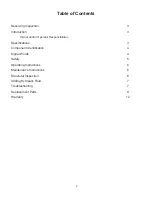
Page 2: ...Owner and or Operator Responsibilities Specifications 3 Component Identification 4 Signal Words 4 Safety 5 Operating Instructions 6 Maintenance Instructions 6 Structural Inspection 6 Adding Hydraulic...

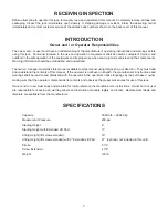
Page 3: ...make this manual available to all personnel using this jack at your direction They must read and understand the contents of this manual If the operator is not fluent in English the manufacturer s ins...

Page 4: ...ous injury This signal word is to be limited to the most extreme situations WARNING Indicates a hazardous situation which if not avoided could result in death or serious injury CAUTION Indicates a haz...

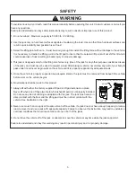
Page 5: ...never begin work on the vehicle until it is properly supported by adequate stands 5 Once the vehicle is properly supported be adequate stands the jack must be removed from beneath the vehicle before...

Page 6: ...ENANCE INSTRUCTIONS Check oil level in the oil reservoir Refer to the Adding Hydraulic Fluid section All warning and capacity labels should be readable and complete Wash external surfaces of jack and...

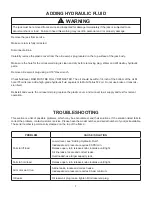
Page 7: ...2 oil Do not use brake or transmis sion fluid Reinstall and secure the oil reservoir plug replace the plastic cover and connect to air supply and test for normal operation TROUBLESHOOTING This section...

Page 8: ...nce When ordering parts give model number part number and parts description Call or write for current pricing Hein Werner Customer Support 10939 N Pomona Ave Kansas City MO 64153 Phone 816 891 6390 E...

Page 9: ...45 1 2 1 4 735 002 001 3 Extended Saddle Adapter 1 5 1 232 20113 Handle Grip 7 8 ID x 5 2 6 1 232 20107 Handle Grip 5 8 ID x 3 1 2 1 7 1 202 01304 Hex Head Capscrew 7 16 14UNC 2 8 1 203 11204 Hex Nut...

Page 10: ...Unit Replacement Parts Illustration for HW93735 Hydraulic Unit 41 4 12 3 14 13 15 10 9 8 7 6 5 16 17 18 19 20 21 22 23 24 25 25 26 27 3 2 1 28 29 30 31 32 33 18 34 35 36 17 37 38 39 40 A 54 45 44 47 4...

Page 11: ...3 310 11024 Cylinder Air Motor 1 28 1 275 10001 Male Connector 1 8 27NPT 1 29 0 236 00005 Ball 1 4 2 30 8 082 30027 Tubing Nylon 1 4 ODx10 1 2 1 Item Part Description Qty 31 1 274 32001 Oil Filler Scr...

Page 12: ...EVER 3 ANY IMPLIED WARRANTIES INCLUDING WITHOUT LIMITATION THE IMPLIED WARRANTIES OF MERCHANTABILITY AND FITNESS FOR A PARTICULAR PURPOSE SHALL BE LIMITED TO TWO YEARS OTHERWISE THE REPAIR REPLACEMENT...

Reviews: