background image

8. Regulating Linkage 


HELENOS III 

20 

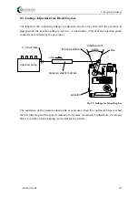
8.4. Linkage Adjustment for Carburettor Engines 

For carburettor or gas engines, the length of the connecting linkage is adjusted in such a 
way that with the governor in full load position the throttle valve is completely open. In 
idling speed position, the elastic link must be slightly overcome. This allows adjustment of 
the idle screw without changing the governor adjustment. 


Patents pending

Range             Voltage

for BasicSystem E

Serial No.

R

Gm bH +  Co.

HEI NZMANN

A m Has elbach 1

D-79677 S chÎnau
Germany

Telef on: (07673)  8208-0
Telef ax : (07673) 8208-88

Diese Schraube darf nicht verstellt werden!

Never turn this screw!

Ne pas toucher a cette vis!

Fül
lu

n

g
F

ue

l
C

ombu

sti

b

le

1

00

50

0

actuator

tension elastic member

displacement

angle

full load position

no load position

throttle valve
opened completely


Fig. 12: Linkage for Gas Engines 


If carburettor or injektion pump are to the right of the governor as opposed to their position 
on the drawings, then the direction of motion of the elastic link must also be reversed. 

Summary of Contents for DG 162-02

Page 1: ...rties 5228 Manual DG 09 008 e 12 09 Heinzmann GmbH Co KG Engine Turbine Management Am Haselbach 1 D 79677 Sch nau Germany Phone 49 7673 8208 0 Fax 49 7673 8208 188 E mail info heinzmann de www heinzma...

Page 2: ......

Page 3: ...concerning EMI Check the functionality of the existing protection and monitoring systems To prevent damages to the equipment and personal injuries it is imperative that the following monitoring and p...

Page 4: ...lication HEINZMANN expressly disclaim the implied warranties of merchantability and of fitness for any particular purpose even if HEINZMANN have been advised of a particular purpose and even if a part...

Page 5: ...n devices operating independently of the electronic speed governor Such devices are absolutely indispensable in order to protect operating personnel against injuries and the engine against damages tha...

Page 6: ...System DG 302 02 Basic System DG 402 02 Control Unit DC 162 02 Control Unit DC 302 02 Control Unit DC 402 02 Actuator StG 16 Actuator StG 30 Actuator StG 40 Setpoint Pot SW Setpoint Pot SW Setpoint Po...

Page 7: ...peed Setpoint Potentiometer SW 02 10 B 8 5 3 Setpoint Value Adjustment by Current Signal 9 5 4 Setpoint Value Adjustment by Pedal 9 5 5 Pressure Sensors 9 5 6 Temperature Sensor TS 2000 F for Measurin...

Page 8: ...Held Programmer 2 37 10 3 Programming by PC 37 10 4 Programming with User Masks 37 10 5 Transferring Data Sets 38 11 Starting the Engine Brief Instructions 39 12 Ordering Specifications 40 12 1 Gener...

Page 9: ...on and the maximum fuelling position electric catches can be provided This will prevent the governor s thrust from affecting the terminal stops of the injection pump etc d Speed Dependent Fuel Limitat...

Page 10: ...nce on speed resp load l Anti Stick Slip Device For locomotive operation an anti stick slip device can be provided m Accessories Accessories such as synchronizing units load measuring units disturbanc...

Page 11: ...r indicates the current position of the output shaft thus allowing optimum signal adjustment by the CPU As the governor comprises an I fraction and as for any load level the speed is permanently compa...

Page 12: ...3 Block Diagram of the Digital Governor HELENOS III 4 3 Block Diagram of the Digital Governor DG 162 up to DG 402 Fig 1 Blockdiagram DG 162 up to DG 402...

Page 13: ...s DG 162 02 DG 302 02 and DG 402 02 are designed for a maximum frequency of 12000 Hz Frequency by Hz is calculated according to the formula f Hz n z min 1 60 z number of teeth on the pick up wheel Exa...

Page 14: ...re valid Due to tolerances a radial arrangement of the magnetic pick up is preferable 4 4 Clearance of Magnetic Pick up The distance between the magnetic pulse pick up and the tooth top should range f...

Page 15: ...ng specification e g IA 02 76 4 6 Redundant Speed Signal If precautions are to be taken with regard to failures of the pulse pick up a second pulse pick up can be connected to the control unit In case...

Page 16: ...splacement angle approx 312 Potentiometer resistance 5 kOhm Limitation resistance 2 x 470 Ohm Temperature range 55 C to 120 C Protection grade IP 00 9 5 3 8 32 NEF 2A 27 23 26 Fig 4 Potentiometer SW 0...

Page 17: ...ted to the control unit If the signal fails the governor will set the speed to a programmable substitute value 5 4 Setpoint Value Adjustment by Pedal This unit is basically an angular position transdu...

Page 18: ...ting current approx 1 mA Time constant in fluids approx 13 s Admissible socket temperature range 40 C to 105 C Protection type IP 65 Vibration 10 g 10 100 Hz Shock 50 g 11 ms half sine wave Tightening...

Page 19: ...ent of actuator at 24 V DC Operating Ambient Temperature 40 C to 70 C Storing Temperature 55 C to 85 C Humidity up to 100 Control Frequency 200 to 12 000 Hz Steady State Variation 0 25 of rated speed...

Page 20: ...connectors DC 2 02 55 205 260 240 25 110 160 6 5 92 42 20 55 130 HEI NZMANN Serial No for Basic System E Range Voltage GmbH Co Am Haselbach 1 D 79677 Sch nau Schwarzwald Germany Phone 0 76 73 82 08 0...

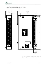
Page 21: ...6 Control Unit HELENOS III 13 Control Unit with terminal strip DC 2 02 00 Fig 8 Housing of DC 162 02 00 up to DC 402 02 00...

Page 22: ...g time lubricants assures maintenance free operation and long working life of the actuators A feedback cam is mounted on the governor output shaft which is scanned contactlessly by a probe thus transm...

Page 23: ...n change of load Indifference to slow voltage changes of the supply abrupt voltage changes cause governor disturbances 7 2 Installation The actuator must be mounted firmly on the engine by means of re...

Page 24: ...ate condition approx 1 A approx 1 A approx 1 5 A on change of load approx 3 4 A approx 3 4 A approx 4 5 A max current approx 4 5 A approx 4 5 A approx 6 A in current limitation approx 2 5 A approx 2 5...

Page 25: ...au Germany Telefon 07673 8208 0 Telefax 07673 8208 88 Diese Schraube darf nicht verstellt werden Never turn this screw Ne pas toucher a cette vis 216 30 SAE Serration 1 2 36 238 M8 66 18 2 11 70 79 5...

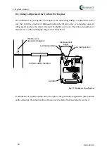
Page 26: ...ng the travel distance of the injection pump or the carburettor 8 2 Connecting Linkage The connecting linkage from the governor to the injection pump or the carburettor should be length adjustable and...

Page 27: ...bach 1 D 79677 Sch nau Germany Telefon 07673 8208 0 Telefax 07673 8208 88 Diese Schraube darf nicht verstellt werden Never turn this screw Ne pas toucher a cette vis F llung Fuel Combustible 1 0 0 50...

Page 28: ...s pending Range Voltage for BasicSystem E Serial No R Gm bH Co HEINZMANN Am Haselbach 1 D 79677 Sch nau Germany Telefon 07673 8208 0 Telefax 07673 8208 88 Diese Schraube darf nicht verstellt werden Ne...

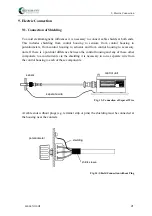
Page 29: ...ntrol housing and any of these other componets to avoid currents via the shielding it is necessary to run a separate wire from the control housing to each of these components HEINZMANN Serial No for B...

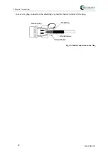
Page 30: ...ectric Connection HELENOS III 22 In case of a plug connection the shielding is jamed in the strain relief of the plug Sensor plug Strain Relief Shielding Shrink Sleeve Fig 15 Shield Connection in the...

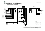
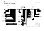
Page 31: ...ectric Connection Helenos III 23 9 2 Connection for Generator Set with digital Accessories Example for parallel and mains operation Fig 16 Connections with Plugs IP 55 for Genset with Digital Accessor...

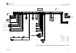
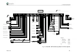
Page 32: ...9 Electric Connection Helenos III 24 Fig 17 Connections with Terminal Strip IP 00 for Genset with Digital Accessories...

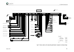
Page 33: ...ctric Connection Helenos III 25 9 3 Connection for Generator Set with analoque Accessories Example for parallel and mains operation Fig 18 Connections with Plugs IP 55 for Genset with Analogue Accesso...

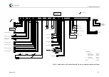
Page 34: ...9 Electric Connection Helenos III 26 Fig 19 Connections with Terminal Strip IP 00 for Genset with Analogue Accessories...

Page 35: ...9 Electric Connection Helenos III 27 9 4 Connection for Vehicle Operation Example Fig 20 Connections with Plugs IP 55 for Vehicle Operation...

Page 36: ...9 Electric Connection Helenos III 28 Fig 21 Connections with Terminal Strip IP 00 for Vehicle Operation...

Page 37: ...9 Electric Connection Helenos III 29 9 5 Connection for Locomotive Operation 16 Speed Levels Example for 16 speed levels Fig 22 Connections with Plugs IP 55 for Locomotive with Speed Steps...

Page 38: ...9 Electric Connection Helenos III 30 Fig 23 Connections with Terminal Strip IP 00 for Locomotive with Speed Steps...

Page 39: ...ric Connection Helenos III 31 9 6 Connection for Locomotive Operation with Current Signal Example for speed adjustment by current signal Fig 24 Connections with Plugs IP 55 for Locomotive with Current...

Page 40: ...9 Electric Connection Helenos III 32 Fig 25 Connections with Terminal Strip IP 00 for Locomotive with Current Input...

Page 41: ...Electric Connection Helenos III 33 9 7 Connection for Marine Operation Twin Operation Example for twin operation 2 engines with 1 propeller Fig 26 Connections with Plugs IP 55 for Marine Twin Operatio...

Page 42: ...9 Electric Connection Helenos III 34 Fig 27 Connections with Terminal Strip IP 00 for Marine Twin Operation...

Page 43: ...9 Electric Connection Helenos III 35 9 8 Connection for Marine Operation Single Engine Example for single engines Fig 28 Connections with Plugs IP 55 for Marine Single Operation...

Page 44: ...9 Electric Connection Helenos III 36 Fig 29 Connections with Terminal Strip IP 00 for Marine Single Operation...

Page 45: ...elopment and for serial adjustment as well as for service purposes 10 3 Programming by PC Programming can also be performed using the PC In comparison with the hand held programmer this method offers...

Page 46: ...Sets Once programming with respect to a specific engine type and its application has been completed the data set can be stored in the hand held programmer or on diskette For future cases of similar a...

Page 47: ...ained Increse derivative D fraction up to instability and reduce until stability is attained With these values set engine speed is to be disturbed briefly e g by shortly pressing the stop switch and t...

Page 48: ...f usage parameters such as speeds and number of teeth on the flywheel sensors such as speed probes pressure and temperature sensors limitation curves additional functions monitoring funktions input ou...

Page 49: ...12 Ordering Specifications Helenos III 41 12 2 Harness Fig 30 Harness with Cable Numbers...

Page 50: ...12 Ordering Specifications 42 Helenos III 12 3 Plug Connections Fig 31 Plugs with Designation...

Page 51: ...with terminal strip IP00 a L1 Control unit battery L 1 Control unit battery cm Cable size up to 15 m 2 x 2 50 mm over 15 30 m 2 x 4 00 mm b L2 Control unit actuator L 2 1 Control unit actuator feedbac...

Page 52: ...unit boost pressure cm 3 x 0 75 mm L 5 4 Control unit oil pressure cm 3 x 0 75 mm f L6 Control unit digital inputs L 6 1 Control unit switch 1 4 cm 5 x 0 75 mm L 6 2 Control unit switch 5 8 cm 5 x 0 7...

Page 53: ...mm L 10 4 Control unit display speed A cm 2 x 0 75 mm L 10 5 Control unit load sharing cm 2 x 0 75 mm L 10 6 Control unit controll pitch propeller cm 2 x 0 75 mm k L11 Control unit frequency input L...

Page 54: ...bach 1 D 79677 Sch nau Germany Please include the following information your name name and address of your company e mail or address where you want the manuals to be sent to if different from above it...

Reviews: