background image


Heinzmann GmbH & Co. KG 


Engine & Turbine Controls 


Am Haselbach 1 


D-79677 Schönau (Schwarzwald) 


Germany 


Phone 

+49 7673 8208-0 


Fax 

+49 7673 8208-188 


Email 

info@heinzmann.com 


www.heinzmann.com 


V.A.T. No:  DE145551926 


HEINZMANN

®


Engine & Turbine Controls 


KRONOS 20 


Electronically controlled 

Air Fuel Ratio Control System 

for Gas Engines 

with open / closed Control Loop 


Copyright 2007 by Heinzmann GmbH & Co. KG All rights reserved. This publication may not be reproduced by any means whatsoever or 
passed on to any third parties. 

Manual AFR 03 002-e / 01-08

Summary of Contents for E-LES 30

Page 1: ...w heinzmann com V A T No DE145551926 HEINZMANN Engine Turbine Controls KRONOS 20 Electronically controlled Air Fuel Ratio Control System for Gas Engines with open closed Control Loop Copyright 2007 by...

Page 2: ......

Page 3: ...oncerning EMI Check the functionality of the existing protection and monitoring sys tems To prevent damages to the equipment and personal injuries it is imperative that the following monitoring and pr...

Page 4: ...lication HEINZMANN expressly disclaim the implied warranties of merchant ability and of fitness for any particular purpose even if HEINZMANN have been advised of a particular purpose and even if a par...

Page 5: ...rain 9 3 Sensors 10 3 1 Overview Table 10 3 2 Speed Pickup IA 10 3 2 1 Technical Data 10 3 2 2 Mounting Position 11 3 2 3 Tooth Shape 11 3 2 4 Distance of the Speed Pickup 11 3 2 5 Dimensional Drawing...

Page 6: ...ignal CH4 signal 33 6 1 3 Wiring Diagram for KRONOS 20 with Sensor Signal 34 6 2 Cable Harness 35 6 3 Enclosed Cables 36 6 3 1 Cable W2 to Gas Valve E LES 36 6 3 2 Cable W3 to Pressure Temperature Sen...

Page 7: ...ilure 53 13 3 Error Memories 55 13 4 Bootloader 56 13 4 1 Bootloader Start Tests 56 13 4 2 Bootloader Communication 57 13 5 Error Parameter List 58 14 Parameter Description 65 14 1 Synoptical Table 65...

Page 8: ......

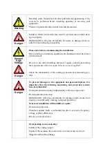
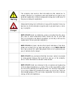
Page 9: ...tri cal high tension Mortal danger This symbol does not refer to any safety instructions but offers important notes for better understanding the functions that are being discussed They should by all m...

Page 10: ...s it is in perfect condition On detecting any faults please inform your superior immediately Before starting the engine remove any unnecessary material and or objects from the working range of the ins...

Page 11: ...3 Before Putting an Installation into Service after Maintenance and Repair Works Check on all slackened screw connections to have been tightened again Make sure the control linkage has been reattache...

Page 12: ...egrated programmer CAN communication Extends application range of existing gas mixers mixing inserts therefore may be used for different gas qualities within a certain range The mixture control system...

Page 13: ...tional gas mixer from KRONOS 10 This system components may only be combined with gas mixers that meet the HEINZMANN specifications If a different gas mixer shall be used con sult HEINZMANN 2 4 System...

Page 14: ...atural gas 34 MJoule nm landfill gas 18 MJoule nm propane 90 Mjoule nm The volume flow rate of the E LES gas valve depends on the gas mixer and its design The indicated performance range is valid only...

Page 15: ...the mixture flow may be calculated The stored gas data and the mixer and gas valve characteristics allow to calculate current pressure conditions and gas flow This al lows a mixture control according...

Page 16: ...l Functions Engine Stop On activation of the digital input for engine stop the gas valve will be completely closed in dependence of the parameter settings until the engine stops But usually the engine...

Page 17: ...n is available 2 8 Gas Train The components of the gas train such as magnetic valve gas filter and in particular zero pressure regulator constitute a unity in an optimally working system of gas regula...

Page 18: ...10 V AC 0 3 4 8 V 0 50 kOhm 0 900 mV Operating tem perature range 8 to 120 C 40 to 130 C up to 800 C In order to allow sufficient flexibility and comparability of sensors the min max values of pressu...

Page 19: ...up the speed without alteration e g by being mounted on the starter gear of the flywheel The pickup wheel must be made of magnetic material e g steel or cast iron 3 2 3 Tooth Shape Tooth shape is opt...

Page 20: ...mensional Drawing G L 35 19 Figure 3 Dimensions of the Speed Pickup Unit Type L mm G Notes 01 38 38 M 16 x 1 5 02 76 76 M 16 x 1 5 connector 03 102 102 M 16 x 1 5 used 11 38 38 5 8 18UNF 2A SV6 IA 2K...

Page 21: ...B IA 02 76 II3G Ex nA II T4 Tcable 5 C to 80 C Thousing 8 C to 120 C T V 06 ATEX 552893 WARNING EXPLOSION HAZARD DO NOT DISCONNECT WHILE CIRCUIT IS LIVE UNLESS AREA IS KNOWN TO BE NON HAZARDOUS Figur...

Page 22: ...3 2 Dimensional Drawing 600 00 082 00 HEINZMANN 2 1 3 4 27 8 19 6 46 5 9 12 05 0 08 60 14 12 48 6 7 20 9 12 22 15 Figure 5 Dimensional Drawing of Double Sensor P T S 01 Sensor hole diameter 12 5 0 1 m...

Page 23: ...done by HEINZMANN too In this case HEINZMANN will attach the following sticker to the wire close to the sensor plug HEINZMANN GmbH Co KG Germany www heinzmann de Tel 49 7673 8208 0 Type P T S 01 II3G...

Page 24: ...or output In unfavourable conditions ground circuit loops may hap pen that falsify the output signal considerably and thus disturb con trol activity This must be taken into account during commissionin...

Page 25: ...3 Sensors KRONOS 20 17 3 4 2 Dimensional Drawing 12 22 6 M18x1 5 10 5 28 2 21 8 SW 22 66 2500 2300 73 Figure 7 Dimensional Drawing Sensor LSM 11...

Page 26: ...consumption max 1 A Admissible voltage drop at max power consumption max 10 at control unit Fuse 6 A Storage temperature 40 C to 85 C Operating temperature 40 C to 80 C Air humidity up to 98 at 55 C...

Page 27: ...U1 6 5 V Rpd 100 k Digital input engine stop U0 2 V U1 6 0 V Rpd 4 75 k terminal 11 or Rpu 4 75 k or Rpd 150 k Speed input terminal 13 for inductive sensors with fi 25 to 9000 Hz Ui 0 5 to 30 V AC MAP...

Page 28: ...P1 0V Tmp 0V 5V SpA 0V SpD Err Stp 0V Pu 0V FbC FbM FbR 0V Act Batt GND GND GND REF GND GND MAP GND STOP DI CANH CANL 6A Serial No Type No V PH2 PH1 MAT CL IN 45 118 5 5 40 KRONOS 20 A 22 21 20 19 17...

Page 29: ...pA 0V SpD Err Stp 0V Pu 0V FbC FbM FbR 0V Act Batt GND GND GND REF GND GND MAP GND STOP DI CANH CANL 6A Serial No Type No V PH2 PH1 MAT CL IN 45 118 5 5 40 KRONOS 20 A sensor Heating 22 21 20 19 17 16...

Page 30: ...d to easy accessibility of the connection terminals and to the possibility of having to substitute the unit on site Mount ing position is optional When the unit is mounted directly on the engine it mu...

Page 31: ...design only the forces of friction of the valve itself act on the piston The shaft of the stepping motor is sealed against gas leakage The control electronics of the stepping motor is mounted directl...

Page 32: ...at max power consumption Fuse 6 A Stepping motor frequency 500 Hz Storage temperature 40 C to 85 C Ambient temperature during operating 20 C to 80 C Air humidity up to 98 at 55 C Admissible pressure o...

Page 33: ...seconds Weight approx 1 kg 5 2 3 Additional Specifications for Gas Valve E LES 50 Valve resolution 2000 steps at 10 revolutions Positioning time for 0 100 4 seconds Weight approx 1 8 kg 5 2 4 Addition...

Page 34: ...32 138 48 48 94 32 48 60 42 5 10 DO NOT DISCONNECT WHILE CIRCUIT IS LIVE UNLESS AREA IS KNOWN TO BE NON HAZARDOUS WARNING EXPLOSION HAZARD BEFORE REMOVING THE COVER SWITCH OFF THE POWER SUPPLY AND WAI...

Page 35: ...5 Gas Valves E LES KRONOS 20 27 1 2 3 4 5 6 7 GND 138 114 71 5 46 5 75 62 5 32 5 80 85 DIN 2999 R2 48 5 221 58 5 62 5 25 UB Ph1 Ph2 DIN 2999 Rp2 Figure 11 Dimensional Drawing E LES 50...

Page 36: ...Valves E LES 28 KRONOS 20 1 2 3 4 5 6 7 GND UB Ph1 Ph2 80 200 336 105 125 130 76 226 Connection flange fitting to welding neck flange according to DIN 2633 PN 16 DN 80 Figure 12 Dimensional Drawing E...

Page 37: ...out exclusively by trained per sonnel and in conformity with current standards and requirements The mounting position must be chosen in a way to avoid vibration and pulsation as much as possible In a...

Page 38: ...and serial number Type z B E LES 50 Serial No yy mm xxxx zz Figure 14 Sign with Type Designation and Serial Number Sign 3 on the control cover contains warnings about disconnecting the plug and re mo...

Page 39: ...HEINZMANN and by the plant builder Only specified cable types may be used for wiring All indicated cable cross sections must be adhered to at all costs The control valve is controlled by a HEINZMANN c...

Page 40: ...20 21 12 24 V 2 1 5 6 KRONOS 20 E LES Electronically controlled MAS Battery Fuse 6 A Governor on Control Unit Engine Stop Common Alarm 3 4 7 3 2 4 1 Boost Pressure Sensor Temperature Sensor A B Magne...

Page 41: ...V 2 1 5 6 KRONOS 20 E LES Electronically controlled MAS Battery Fuse 6 A Governor on Control Unit Engine Stop Common Alarm 3 4 7 3 2 4 1 Boost Pressure Sensor Temperature Sensor A B Magnetic Pickup IA...

Page 42: ...cally controlled MAS Battery Fuse 6 A Governor on Control Unit Engine Stop Summenalarm 3 4 7 3 2 4 1 Boost Pressure Sensor Temperature Sensor A B Magnetic Pickup IA Lambda Signal 5 4 2 3 T x D R x D 2...

Page 43: ...ions W 1 power supply max length 15 m 2 x 1 50 mm W 2 gas valve control max length 15 m 4 x 0 75 mm W 3 pressure temperature sensor max length 15 m 4 x 0 75 mm W 4 speed pickup 2 x 0 75 mm W 5 actual...

Page 44: ...by HEINZMANN in the required length 6 3 1 Cable W2 to Gas Valve E LES 1 2 3 4 5 6 7 GND UB Ph1 Ph2 Length on request max 15 m Housing 2 1 21 20 1 2 4 5 Ground UB Phase 2 Phase 1 Screen brown green ye...

Page 45: ...W3 to Pressure Temperature Sensor P T S 01 Length on request max 15 m Housing 16 6 4 15 1 2 3 4 Ground NTC Signal 5V Pressure Signal Screen brown white green yellow Terminal Plug Pin Function Colour T...

Page 46: ...ic Connection 38 KRONOS 20 6 3 3 Cable W4 to Speed Pickup IA Length on request max 15 m Housing 13 12 A B Signal Ground Screen 1 2 Terminal Plug Pin Function No Terminal Assignment of Cable Figure 22...

Page 47: ...4 Cable W5 to Sensor LSM 11 19 18 8 7 Sensor Sensor Heater Heater yellow green white black Terminal Function Colour Terminal Assignment of Cable yellow white brown A A green Length on request max 15 m...

Page 48: ...e control unit 7 1 Parametrization with the Hand Held Programmer 3 All parametrization can be done by means of the hand held programmer Programmer 3 This handy device is particularly suited for develo...

Page 49: ...st be tightened All components must be connected to equipotential bonding All components must be installed only in the allowed areas All components must be installed in a way to protect their connecto...

Page 50: ...cover is mounted 9 2 General Information on the first Engine Start Adjust speed pickup distance according to the instructions Verify that the software is correct and the main parameters engine data nu...

Page 51: ...tion with a closed loop a com plete calibration is necessary The actual measured values must correspond to the variables and set values of the mixture control For this calibration the following device...

Page 52: ...hanged to set 1 70 4 Verify the lambda values 5 If mea des repeat steps 1 to 4 When mea des then 1 Reduce vent 1424 VenturiEfficiency until mea des or to the lower ignition limit Attention danger of k...

Page 53: ...ues des 3462 LambdaDesiredValue must not necessarily correspond to the actual measured values cal 3463 LambdaActualValue Variations up to 20 are acceptable This is also true for other values such as c...

Page 54: ...the other three load points e g 80 60 and 40 load 3 When Closed Loop is active the system switches automatically to Open Loop as soon as output is inferior to e g 40 depending on 1400 ClosedLpPowerMi...

Page 55: ...ng as the lambda sensor is not ready for operation yet when the sensor has failed or if closed loop operation has not been activated yet 5400 ClosedOrOpenLoop During calibration of the open loop close...

Page 56: ...igh idle speed 7 To achieve optimal starting behaviour the respective map values for the motor start range pressure is 1 bar at low speed are corrected in order to have the engine starting correctly i...

Page 57: ...linders must ignite correctly The function 4050 SpeedVarDetectOn must be active and the functions 4055 MisfireWarnCurveOn and 4056 MisfireEcyCurveOn must be dis abled 2 Raise parameter 50 SpeedVarSamp...

Page 58: ...cy P x Draw the warning characteristic and shutoff characteristic between the two limit characteris tics and record the respective values in 6010 MisfireWarn nVar x and 6030 Mis fireEcy nVar x Enable...

Page 59: ...arly Concentration of hydrogen sulphide H2S in fuel must not exceed 0 1 The gas must be dry When using biogasis used as fuel gas bearing components and sections of the system must be inspected twice a...

Page 60: ...ressive fuels valves should be checked more frequent Check whether the valve runs smooth when turning the handwheel while the engine is still The state of pistons and cylinder face should additionally...

Page 61: ...ors may be due to defective components or other inadmissible operating conditions Under normal circumstances they are not likely to occur To cancel an error one should first establish and eliminate it...

Page 62: ...error categories are sigalled by the following tow parameters 3800 EmergencyAlarm Emergency alarm 3801 CommonAlarm Common alarm The parameter 3801 CommonAlarm will be set on the occurrence of any erro...

Page 63: ...condition data As a standard the following four measurements at the time of occurring the failure will be stored 2000 Speed Current speed value 2302 StepperPos Position of stepper motor 2912 Manifold...

Page 64: ...g as these test are being conducted there will be no communication with the device especially when due to some fatal error the pro gramme is caught in an infinite loop For this reason the current test...

Page 65: ...ANN diagnosis tool is possible The cause of the error and the test status can be seen in the parameters 3087 ErrMainCheckSum 1 Error main programme Test 3800 TestStatus 0 Test status 3801 TestValue1 e...

Page 66: ...ts the appropriate actions to be taken to remove the respective error Starting from parameter number 3001 error memory and 3101 permanent error memory the errors are sorted by ascending numbers with t...

Page 67: ...TeethPickUp for number of teeth 3017 ErrManifoldPressure 3117 SErrManifoldPressure Cause Short circuit or cable break at sensor input for manifold pressure Response Error message Common alarm Emergen...

Page 68: ...t for lambda sensor Response Error message Common alarm Emergency operation in Open Loop mode Emergency operation with substitute value or last valid sensor value depending on choosen response mode Er...

Page 69: ...on alarm as warning No control of stepper motor and valve position because of possibility of stepping errors Error is cleared automatically when supply voltage is above minimum voltage Action Check su...

Page 70: ...t 3178 SErrRAMTest Cause Current monitoring of the working memory reports an error Response Error message Emergency alarm by fatal error Emergency operation possible with substitute value for valve po...

Page 71: ...ch on the supply voltage or when reseting 3092 ErrConfiguration 3192 SErrConfiguration Cause Configuration of the programmed parameters are not plausible Response Error message Emergency alarm by fata...

Page 72: ...PTION error Response Error message Emergency alarm by fatal error Emergency operation possible with substitute value for valve position but not advisible Action Write down the values of the parameters...

Page 73: ...Pickup Speed 6000 Misfiring 50 Speed deviation Misfiring 2050 Speed deviation Misfiring 4050 Speed deviation Misfiring 250 Start 2250 Start 300 Stepper Motor 2300 Stepper Motor 4300 Stepper Motor 800...

Page 74: ...811 StopOpenOrClose 828 FunctErrorReset 2828 SwitchErrorReset 2851 DigitalOut1 2852 DigitalOut2 912 AssignIn_MnfldPress 2912 ManifoldPressure 913 AssignIn_MnfldTemp 2913 ManifoldTemp 914 AssignIn_Meas...

Page 75: ...reEcy 3148 SErrPowerSupplyWarn 3161 SErrDigitalOutput1 3162 SErrDigitalOutput2 3176 SErrParamStore 3177 SErrProgramTest 3178 SErrRAMTest 3180 SErrDisplay 3181 SErr5V_Ref 3185 SErrVoltage 3190 SErrData...

Page 76: ...531 AnalogIn3_RefHigh 3531 AnalogIn3_Value 1532 AnalogIn3_ErrorLow 1533 AnalogIn3_ErrorHigh 1534 AnalogIn3_Filter 1540 AnalogIn4_RefLow 3540 AnalogIn4 5540 AnalogIn4_Type 1541 AnalogIn4_RefHigh 3541 A...

Page 77: ...Step 3895 RAMTestAddr 3896 RAMTestPattern 3897 CStackTestFreeBytes 3898 IStackTestFreeBytes 7900 TempIn1 digit 7920 TempIn1 T 9400 VolEffMap n 9410 VolEffMap p 9420 VolEffMap Eta 9500 MechEffMap n 951...

Page 78: ...255 StartSpeed1 Level 4 Range 0 4000 1 min Page s Minimum speed for detection of engine start Gas valve will be activated 256 StartSpeed2 Level 4 Range 0 4000 1 min Page s Minimum speed for detection...

Page 79: ...t to function Reset errors 912 AssignIn_MnfldPress Level 6 Range 0 5 Page s Assignment of input channel to manifold pressure 913 AssignIn_MnfldTemp Level 6 Range 0 5 Page s Assignment of input channel...

Page 80: ...ensor 993 CH4ContentSensorHigh Level 4 Range 0 100 Page s Max value of CH4 sensor 1012 SubstMnfldPressure Level 4 Range 0 5 bar Page s Substitute value for manifold pressure in case of sensor failure...

Page 81: ...of the engine 1413 MechEfficiencyConst Level 4 Range 0 1 0 5 Page s Constant value for mechanical efficiency of the engine 1420 ThroatArea Level 4 Range 300 30000 mm Page s Throat area of gas mixer i...

Page 82: ...gas quality the calibration value will be used 1452 LambdaStoichConst Level 2 Range 1 30 m m Page s Constant lambda stoichiom value At changing gas quality the calibration value will be used 1460 Lamb...

Page 83: ...0 5 V Page s Low reference value of analogue input 4 Standard for manifold pressure Here set for 0 5 V 1541 AnalogIn4_RefHigh Level 4 Range 0 5 V Page s High reference value of analogue input 4 1542 A...

Page 84: ...0 steps Page s Setpoint for stepper position in positioner mode 1706 StepPositionerAmpl Level 4 Range 0 0 steps Page s Amplitude for stepper position in positioner mode 1707 StepPositionerTime Level 4...

Page 85: ...rPos Level 4 Range 0 4000 steps Page s Actual stepper position 2331 StepperPosAbsMax Level 4 Range 0 4000 steps Page s Absolute max position of stepper motor depending on E LES type 2332 StepperPosSet...

Page 86: ...lue of measured power 2915 Lambda Level 1 Range 0 2 5 Page s Actual value of lambda sensor 2916 CH4Content Level 1 Range 0 100 Page s Actual value of CH4 content 3000 ConfigurationError Level 1 Range...

Page 87: ...s Alarm indication due to misfiring 3048 ErrPowerSupplyWarn Level 1 Range 0 1 Page s Error indication of low power supply voltage Anzeige der Unterspannungswarnung 3061 ErrDigitalOutput1 Level 1 Range...

Page 88: ...Range 0 1 Page s Error indication for software configuration 3093 ErrStack Level 1 Range 0 1 Page s Error indication for stack overflow 3094 ErrIntern Level 1 Range 0 1 Page s Error indication for int...

Page 89: ...ange 0 255 Page s Sentinel for the occurrence of 3046 ErrMisfireWarn 3147 SErrMisfireEcy Level 1 Range 0 255 Page s Sentinel for the occurrence of 3047 ErrMisfireEcy 3148 SErrPowerSupplyWarn Level 1 R...

Page 90: ...0 255 Page s Sentinel for the occurrence of 3090 ErrData 3192 SErrConfiguration Level 1 Range 0 255 Page s Sentinel for the occurrence of 3092 ErrConfiguration 3193 SErrStack Level 1 Range 0 255 Page...

Page 91: ...tureFlowRate Level 1 Range 0 25000 m n h Page s Calculated mix flow 3411 CalculatedPower Level 1 Range 0 2500 kW Page s Calculated generator power 3412 VolumetricEfficiency Level 1 Range 0 5 1 Page s...

Page 92: ...c value variation only at CH4 con tent feedback 3452 LambdaStoichiometric Level 1 Range 1 30 m m Page s Current gas lambda stoichiometric variation only at CH4 content feedback 3453 GasFlowRateDesired...

Page 93: ...Unnormalized value of analogue input 3 3540 AnalogIn4 Level 1 Range 0 100 Page s Normalized value of analogue input 4 3541 AnalogIn4_Value Level 1 Range 0 5 V Page s Unnormalized value of analogue inp...

Page 94: ...age s Indication when engine is started 3805 EngineRunning Level 1 Range 0 1 Page s Indication when engine is running 3806 EngineReleased Level 1 Range 0 1 Page s Indication when AFR control is releas...

Page 95: ...grammer 3865 CalculationTime Level 1 Range 0 16 384 ms Page s Value of remaining calculation time for main processor 3870 Timer Level 1 Range 0 65 535 s Page s Internal clock 3871 OperatingHourMeter L...

Page 96: ...14 Parameter Description 88 KRONOS 20 No Name Signification 3898 IStackTestFreeBytes Level 6 Range 0000 0200 Hex Page s Indication of free bytes in I stack...

Page 97: ...plied 1 Stop active by one single switch pulse until engine stops 4811 StopOpenOrClose Level 6 Range 0 1 Page s Switch function engine stop is active if switch is 0 opened 1 closed 5012 SubstOrLastMnf...

Page 98: ...matically reset 1 error is to be held 5055 HoldOrResetLambda Level 4 Range 0 1 Page s Selection whether the error at lambda sensor is to be held or automatically reset 0 to be automatically reset 1 er...

Page 99: ...5530 AnalogIn3_Type Level 6 Range 1 2 Page s Signal type of analogue input 3 1 0 5 V 2 0 22 7 mA 5540 AnalogIn4_Type Level 6 Range 0 1 Page s Signal type of analogue input 4 0 0 65535 Digits 1 0 5 V...

Page 100: ...ambdaMap n x up to 7409 Level 4 Range 0 4000 1 min Page s Speed values for lambda map 7450 LambdaMap p x up to 7459 Level 4 Range 0 5 bar Page s Manifold pressure values for lambda map 7500 LambdaMap...

Page 101: ...Range 0 5 bar Page s Manifold pressure values for mechanical efficiency map 9520 MechEffMap Eta x up to 9583 Level 4 Range 0 1 0 5 Page s Mechanical efficiency values for mechanical efficiency map 960...

Page 102: ...l drawing of control unit KRONOS 20 with sensor input 21 Figure 10 Dimensional Drawing E LES 30 26 Figure 11 Dimensional Drawing E LES 50 27 Figure 12 Dimensional Drawing E LES 80 28 Figure 13 Sign be...

Page 103: ...st certificates T V 06 ATEX 552893 and T V 07 ATEX 552892 X complies with the requirements of Directive 94 9 EC of the European Parliament and Commission of March 23rd 1994 on the approximation of the...

Page 104: ...17 Order Form for KRONOS Systems 96 KRONOS 20 17 Order Form for KRONOS Systems...

Page 105: ...any you can simply include your business card the address where you want the manuals sent if different from above the number s as on front page bottom right and title s of the desired manual s or the...

Page 106: ...ls Quantity No of the manual Title Please send me your new sales documentation about the HEINZMANN Analogue Governors Application the HEINZMANN Digital Governors Application the HEINZMANN Gas Engine E...

Reviews: